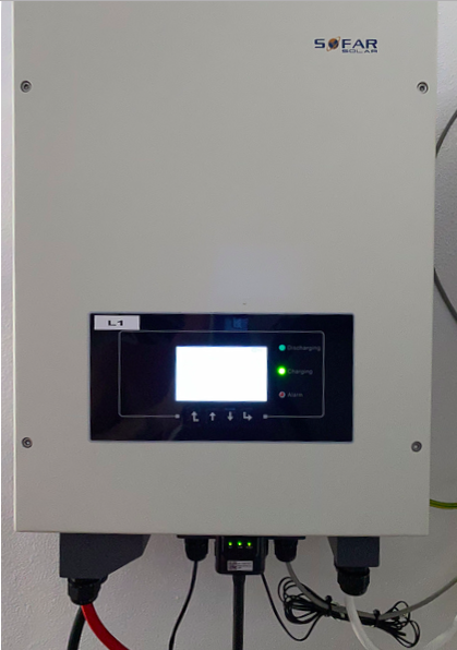
Some useful things about this inverter which are not mentioned, or not obvious from the manual. This is based on experience with software version 2.4.
Connecting things up
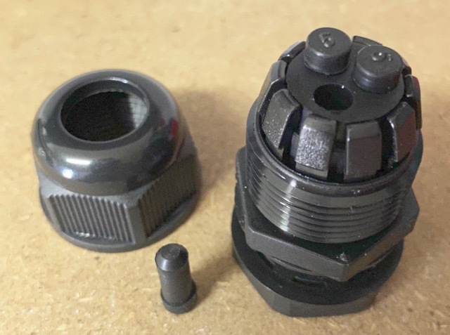
You will need a replacement 20mm cable gland for the mains connection(s) if you are using a 3-core flex as the bung in each cable gland has 3x small holes and so expects 3x single core cables.
The unit comes with 2x M6 cable lugs for 25sqmm DC cables but M8 lugs fit fine (eg. on the end of the Pylontech cables).
Setting up the CTs
The unit comes with 2x CT clamps:
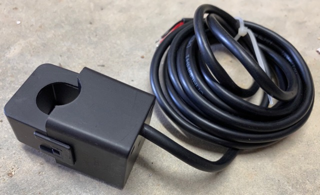
One is for the supply and should be clipped on to your incoming supply live (big fat single-core cable next to your meter). The other is to monitor your generation and so clips to the live wire supply to your PV panels (inside your generation board etc.).
The setup procedure for your inverter includes the steps:
- Make sure all PV is off.
- Turn on battery supply to inverter.
- Turn on mains supply to inverter.
- (now set up time/grid profile/battery)
- Make sure you are consuming at least 200W.
- Turn on the PV and watch it on the display.
What has actually happened here is that the system has worked out which way round the current clamps are (remember you didn’t have to install them a particular way round?)
Now the important part: if you switch off and restart the system, it will go through the same CT configuration again. In fact, there appear to be a number of ‘events’ which cause the CT reconfig:
- Mains off/on
- Battery off/on
- Change work mode
That means that if you cause the CT reconfig when you are exporting power, it will incorrectly read this as an import and then start exporting until it reaches maximum export. Imagine you are currently exporting 2.5kW from your PV – this then ramps up to 2.5kW plus another 3kW from the inverter = 5.5kW export! You do have a G99 relay to stop this don’t you?!?
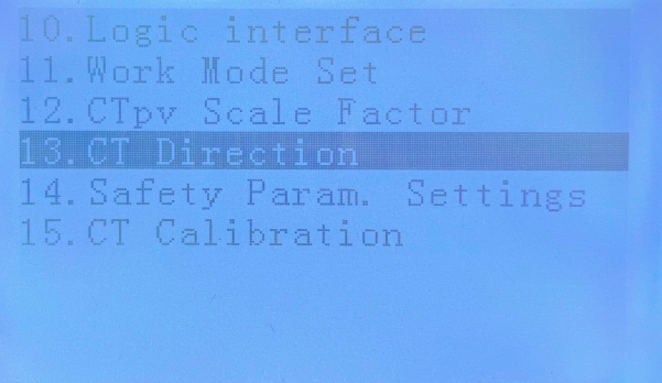
There is a way round this though: FREEZE CT. This is something you should do when you are happy it is configured correctly. Go to Configuration, then down to option 13:
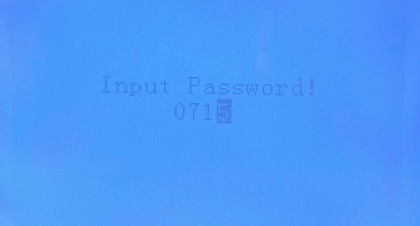
Enter the password:
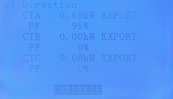
You will see the CTs, and at the bottom ‘UNFREEZE’ (which counter-intuitively means ‘CTs not frozen’:
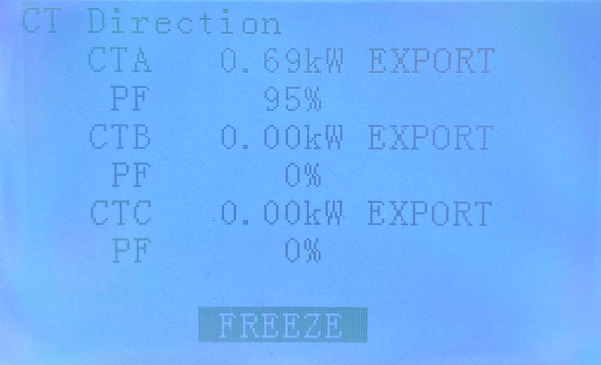
Press the down button to display ‘FREEZE’:
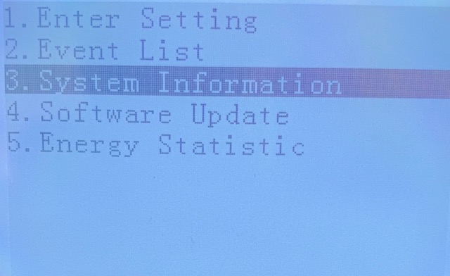
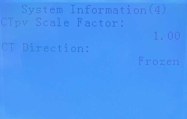
..and then press ‘enter’ to save (then enter again to get off the confirmation screen). You can check the CT direction is frozen from System Information, screen 4:
..which should now show ‘Frozen’:
CTpv isn’t needed
It is possible to use this inverter without the pv sensor. It appears the CTa clamp is the only one used for import/export. This is good news for people who are not able to monitor all (or any) of their generation due to it being connected into different parts of the mains system without a central point for a CT. Obviously you won’t get logged data for the generation and various totals will not be accurate on the system.
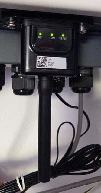
Datalogger
The inverter comes with a datalogger with WiFi. This is something not mentioned in the manual for the inverter. It connects to a DB9 port on the bottom of the unit and once you have it connected to your wifi network, it posts the unit’s data to the Solarman cloud-based system.
Pylontech US3000 and battery capacity
The inverter doesn’t seem to be able to tell the difference between the US2000 and US3000 on the CAN bus at the moment and so incorrectly sets the capacity to 50Ah per battery instead of 75Ah for the larger US3000.
Changing battery settings
Beware: In order to change battery settings, you have to start by selecting the battery type – at this point, the defaults are loaded, overwriting whatever tweaks you previously made. Make sure you go through each parameter again!