(or multiple inverter/chargers connected to one battery pile)
Is it possible to connect multiple ME3000s to one (Pylontech) battery pile? The short answer is: yes, it is possible, but it doesn’t work all that well.
And don’t blame us if you damage your batteries / set fire to your house / etc. The use of this information is entirely at your own risk!
The US2000 / US3000 batteries talk to the Sofar Solar ME3000 inverter/charger using the CAN interface. Theoretically, once the first one inverter/charger is connected to the batteries using CAN and a battery setting of PYLON, any subsequent inverter/chargers can use a battery type of DEFAULT – which is generally used for lead-acid batteries.
Here are some rough battery parameters for the default battery type in this configuration:
- Battery type: DEFAULT
- Battery Capacity: (whatever your battery pile is)
- Discharge Depth: 80%
- Max Charge Current: (calculated as your battery capacity divided by number of ME3000s)
- Over Voltage Protection: 54.0V
- Max Charge Voltage: 51.5V (normally 52.8V but limited to stop over-voltage – see below)
- Max Discharge Current: (same as Max Charge Current)
- Low Voltage Protection: 45.9V
- Min Discharge Voltage: 49.0V (normally 47.2V but higher here to limit over-discharge)
- Empty Discharge Voltage: 46.7V
- Full Charge Voltage: 52.08V
- You also need to have the temperature probe connected (and ideally attached the to case of the top battery pack).
Limitations
Using these settings with a different battery technology poses a number of problems around the battery-protecting charging and discharging limits and also knowing the state of charge (SOC).
Voltage measurement
Knowing the voltage of the batteries is important since this is used by the inverter/charger to ensure the batteries are kept within their operating limits, which ensures they have a long and useful life.
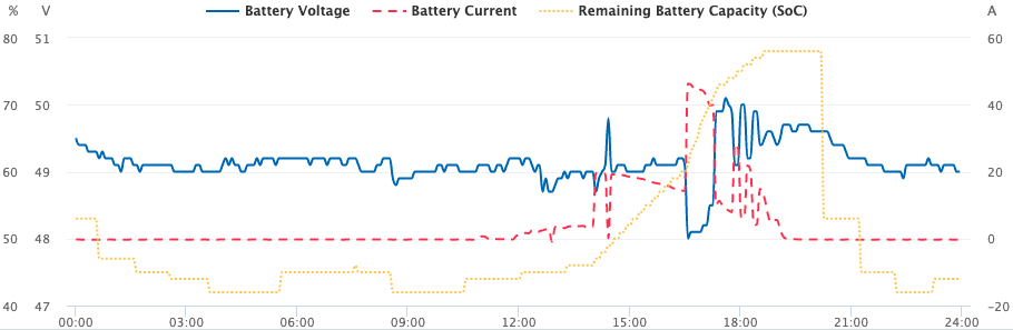
When using the DEFAULT battery setting, this voltage is measured inside the inverter, not inside the batteries. This causes a problem in that the more current is drawn from the batteries, the more the voltage drops due to cable and internal battery resistance. The boffins at Sofar Solar have thought of this though – and they compensate for it. However, they have no idea what the resistance of the cables is, and they think the battery is lead-acid. Have a look at this graph from an ME3000 in DEFAULT mode produced by Solarman covering a 24 hour period and showing SOC, Voltage and Current. The battery current is shown as red in the graph and starts the day at about zero. This is for phase L1.
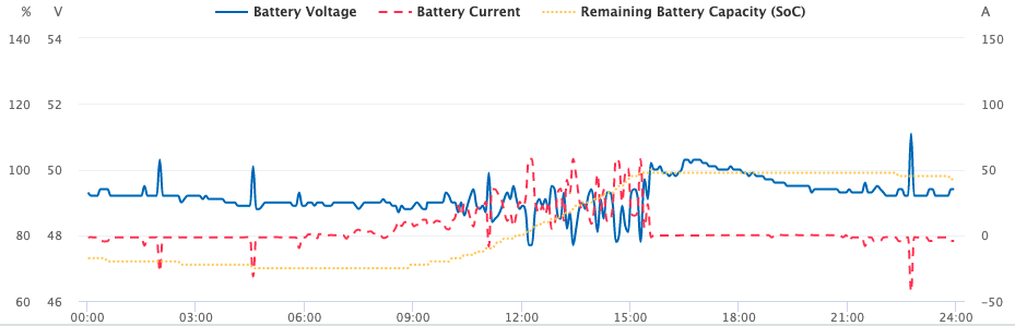
Look at the two negative peaks at about 02:00 and 04:30. When the current is drawn, the voltage goes up! (Specifically, the first 26A draw causes a 1.1V increase, the second 30A draw causes a 1.2V increase.) A battery will not behave like this in real life – clearly the system is over-compensating for the resistance. This has a knock-on effect in our settings – we want to protect the batteries by stopping the voltage dropping too far when the SOC is low, which is done with the Minimum Discharge Voltage. For the PYLON type battery setting, this is minimum is 47.2V and so for DEFAULT we are using 49.0V to compensate in the settings above. This will be system-specific since it depends on battery size, likely current draw and battery cables.
The reverse can also be seen in the charging phase of the day – the voltage drops when charging and so is all over the place. Because during charging the voltage measurement is being artificially reduced, we need to compensate in the Maximum Charge Voltage by reducing it.
Compare the graph above to the inverter on the same battery pile using CAN for its readings over the same period. This is on L3:
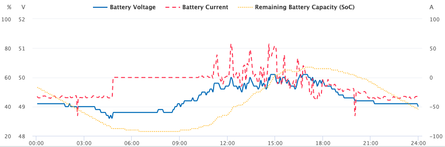
..the early current spike causes no change in the voltage and overall the voltage is far more stable.
State of Charge (SOC) calculations
OK – the inverter can see the battery, its voltage, knows the current being drawn or charged, and knows the capacity of the battery. However, it doesn’t know what any other inverter/chargers are doing and assumes it is the only one. Battery state of charge (SOC) is a calculated figure, whether the batteries are calculating and reporting it, or the inverter/charger is. In our case here, using the DEFAULT battery type, the inverter is attempting to work out the SOC. It only knows about itself, and so its calculations will not be accurate (whereas the battery management in the Pylontech batteries have the full picture).
You can see by comparing the graphs above that the SOC doesn’t look too different. The L3 graph is the accurate one, and the L1 one above shows a similar curve as the battery is charged. However, at the start of the graph (midnight) L1 shows the SOC too low, and after the battery pile is fully charged (15:30) it then remains too high.
Now for three graphs showing L1, L2, L3 on a different day.
The first graph shows L3 – which is connected via CAN to the batteries and shows the true picture:
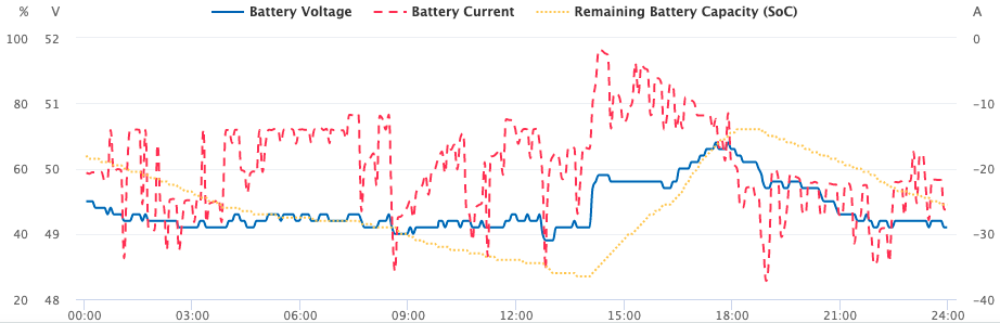
SOC starts at 64% at midnight, dropping to 27% at 13:57 before starting to recharge, where it hits 72% at 18:13 before starting its discharge gain. Throughout the day the inverter is either discharging or charging the battery as the demand or excess on that phase requires. [Note that there is a display problem on the graph – the current scale is incorrect here – 0A is shown as about -15A.]
Here is L1 for the same day:
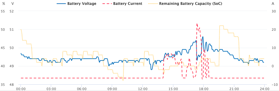
The SOC scale is different, but the day starts at 50%, drops to 36% at 10:04, but generally bears no resemblance to the actual SOC. The load on this phase is very constant. [Here the Solarman system is incorrectly reporting -6A when it should be zero.] Here is L2:
The day starts at 53%, drops to 42% at 03:38, recovers a bit and then starts climbing as charging starts at 11:50, reaching 78% at 18:39. The inverters don’t really have a clue what the SOC is, but seem to be periodically recalculating it based on the changing battery voltage.
Charge rates
For good battery management, charge rates vary depending on SOC. When eg. for LiFePO4 batteries, they are charged at 0.5C until they are close to their maximum charge (90%), then the charge rate is reduced to something like 0.2C. In order for the charger to reduce the charge rate at close to full charge, it needs to accurately know the state of charge.. which we have shown above is not the case with the DEFAULT setting.
Continuing to charge at 0.5C past 90% state of charge is likely to shorten the life of your batteries. But – the charge rate could already be limited by your charger. Each US2000 has a maximum charge rate of 20A and each US3000 a maximum charge of 37A; this is the 0.5C. We can therefore calculate the 0.2C which would be 8A for the US2000 and 14.8A for the US3000. Let’s say you had 10x US3000 – 0.2C would be 148A. If you had 3x ME3000s each set at 50A max charge, you would never exceed 0.2C anyway and so would be safe. If you had 4x US3000, 0.2C would be 4 x 14.8 = 59.2A so you should be more careful. As we have seen above, attempting to control the charge using the battery voltage is difficult because of software compensation of the voltage – during charging the voltage is suppressed. Of course, if your batteries tend not to get close to full charge, this is less of an issue. Also bear in mind that if you have 3x inverter/chargers, one will be connected via CAN and so you are only concerned with the other two. Maybe you can arrange them with your generating equipment so this is not a problem (eg. most generation on the one charger connected via CAN).
Hi,
I really hope a future firmware will allow 2 x Me3000sp to be linked together. I know in the ME3000sp facebook group there’s talk of people trialing it when connected to raspberry pi etc.
Each ME3000SP has a terminated CAN interface. It is be possible to turn off CAN termination on the Pylontechs with a DIP switch, but you still have a problem that 2x inverters are both sending CAN ACKs back to the batteries.
Not sure if this would work..
I’m in the process of getting something like this setup,
I have a DIY battery with a ZEVA BMS (unfortunately now discontinued, but open source) with 1 ME3000sp currently. I also have another CAN device on the CAN network listening to the BMS but also to the SOC that is meant for the inverter. That is built on an ESP32 chip and a waveshare CAN device. Been looking at the code for it I dont see it acting on any CAN Acks. But we shall see when i get it setup!
I suppose using 2 of the waveshare CAN devices, you could do a middleman, listen to the pylontech and then retransmit it onto the second inverter.
A listen-only CAN device will not generate ACKS. Agreed on the last point.
I have a me3000 and a hyd6000 running side by side with two battery piles
Only problem i get is when i draw more than 3kw they tend to charge the me3000 from the hyd but only happens now and again and that’s due to the over supply when the demand stops other than that they work great
Hi Jonathan
have been reading your write ups on sofar ME3000sp
I have purchased three of these units and have just received batteries from Colin Deng in china
i notice that you have said you have two inverters running together which is what i wanted to do
i did want to run all three but reading on the forum people are only speaking about running two
i do use a bit of electric and wanted the 6kw capacity from the two units but did not want it wasted up the grid
any help or diagrams of the best way to install this would be very helpful
i have 3 x 16s battery packs and a fourth one on its way
2 x 304 amp hr
and 1 x 280 amp hr
please advise me if you get a spare moment as it looks like you are the person that knows his stuff on the ME3000sp
kind regards
Gary