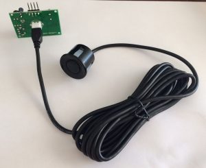
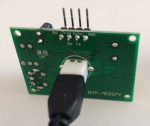
 The serial-output of the DYP-ME007Y ultrasonic range detector is pretty good when you are measuring the distance to a static object with little or no other obstacles creating ‘noise’.
However, the odd spurious reading does crop in from time to time. For example:
201cm
201cm
201cm
128cm
201cm
201cm
201cm
201cm
201cm
201cm
This is actual data, and the spurious 128cm makes no sense and needs to be ignored (rather than just taking an average). Fortunately, @JMMS-Karunarathne and @MikeMeinz wrote some code to correct for this here: https://www.codeproject.com/tips/813946/a-method-to-ignore-anomalies-in-an-ultrasonic-dist
The code takes a group of samples and counts how many of each there are. It then picks the measurement with the highest count (the ‘mode’). In the above example, there are 9 counts of 201cm – which would be returned as the measurement.
So far, so good..
However, there is a problem where all the data is rubbish. Look at this actual data:
275cm
273cm
273cm
275cm
0cm
483cm
0cm
0cm
125cm
235cm
274cm
274cm
274cm
690cm
816cm
274cm
274cm
273cm
0cm
483cm
0cm
274cm
274cm
90cm
184cm
292cm
273cm
539cm
648cm
316cm
This was produced by out-of-range measurements – the object was less than 28cm from the sensor. The measurement which occurred the most was 274cm and so the algorithm would return this seemingly meaningful result.
An improvement to the ‘mode’ routine would be to apply a ‘confidence’ to the measurement. In my code, I take 30 readings, and require a minimum of 20 of the same to accept it as a good measurement. I try this five times over, after which the routine gives up and returns a zero indicating out-of-range. This seems to work well.
Except some of the time. This looks like good data:
82cm
82cm
82cm
82cm
83cm
82cm
82cm
83cm
83cm
83cm
83cm
83cm
83cm
83cm
83cm
82cm
83cm
83cm
83cm
82cm
82cm
83cm
82cm
83cm
82cm
80cm
83cm
83cm
82cm
82cm
confidence was 16
Returning 0cm
Here 83cm was only measured 16 times. This was an absolutely static measurement on the bench, however the returned value was either 82 or 83cm (ignoring the 1x 80cm!).
The way to deal with this is to look at the readings +1 or -1 from the mode. If either the count of the mode, added to the count of the mode+1, or mode-1 adds up to at least the threshold, then the result is good.
UPDATE:
Here is my code to do all this and post the result to an emoncms system using an EPS8266. As you will see, I adapted code from https://www.codeproject.com/tips/813946/a-method-to-ignore-anomalies-in-an-ultrasonic-dist
/*
This sketch sends data via HTTP GET requests to emoncms.
Reads a DYP-ME007Y TX ultrasonic sensor to output distance
data to emoncms
*/
//uncomment this for dev mode
#define DEVMODE 1
// uncomment so disable sending a result when it is the same as the last one (power save etc.)
// #define NO_SEND_SAME 1
#include <ESP8266WiFi.h>
#include <SoftwareSerial.h>
// pin assignments. TX on the arduino connects to RX on the sensor, RX to TX.
#define TX_PIN D6 // D3 // D5
#define RX_PIN D5 // D4 // D6
#define PWR_PIN D3 // for controlling the power to the Ultrasonic.
SoftwareSerial DYPSensor = SoftwareSerial(RX_PIN, TX_PIN);
#define MAX_TRY_SERIAL 50 // how many cycles of 10ms to wait for before giving up on the sensor (up to 255)
#define MAX_TRY_READING 100 // how many times to try getting a confident reading before giving up and reporting zero (up to 255).
// To collect 30 samples and pick the one with the most votes
#define SAMPLES 30 // Defines how many samples are taken before determining the value that appeared the most and then reporting a reading.
#define MIN_VOTES 20 // How many samples need to be the same to return a good result (suggest 2/3 of SAMPLES)
// define blink error numbers..
const int ERROR_WIFI = 4;
const int ERROR_SENSORS = 5;
const int ERROR_HTTP = 6;
const char* ssid = “YOUR_WIFI_SSID”;
const char* password = “YOUR_WIFI_PASSWORD”;
const char* host = “YOUR_EMONCMS_SERVER”;
const char* apikey = “YOUR_EMONCMS_API_KEY”;
const byte node_id = 35;
const int READING_INTERVAL_SECS = 60; // Default = “60” How long to wait between readings, in seconds.
// Global variables
int SamplesIndex = SAMPLES – 1;
int testValues[SAMPLES];
int testVotes[SAMPLES];
long duration;
int distance = 0;
int last_distance = -1;
void setup() {
#if defined(DEVMODE)
Serial.begin(115200);
#endif
pinMode(LED_BUILTIN, OUTPUT); // Initialize the LED_BUILTIN pin as an output
digitalWrite(PWR_PIN, LOW); // to control power to the sensor
delay(10);
// We start by connecting to a WiFi network
#if defined(DEVMODE)
Serial.println();
Serial.println();
Serial.print(“Connecting to “);
Serial.println(ssid);
#endif
WiFi.begin(ssid, password);
while (WiFi.status() != WL_CONNECTED) {
delay(500);
#if defined(DEVMODE)
Serial.print(“.”);
#endif
}
// TODO: report error if unable to connect to WiFi network
// using blink code.
DYPSensor.begin (9600);
#if defined(DEVMODE)
Serial.println(“”);
Serial.println(“WiFi connected”);
Serial.println(“IP address: “);
Serial.println(WiFi.localIP());
Serial.println(“Finished Setup.”);
#endif
digitalWrite(LED_BUILTIN, HIGH);
} // end of setup
//
// Initialize arrays used to store values and “votes”
//
void InitializeTestValues()
{
// Initialize test values arrays
for (int idx = 0; idx <= SamplesIndex; idx++)
{
testValues[idx] = -1;
testVotes[idx] = 0;
}
}
//
// Reads bytes from RX port and returns a reading in cm
// Returns -1 until a correct value is available
//
int GetDistance() {
byte msb, lsb, checksum, checkcalc, tries = 0;
int distance;
#if defined(DEVMODE)
Serial.print(” Getting reading..”);
#endif
// we want a 255 which is the start of the reading (not msb but saving a byte of storage)..
while (msb != 255) {
// wait for serial..
while ( not DYPSensor.available() && tries < MAX_TRY_SERIAL ) {
delay(10);
tries++;
}
if (tries == MAX_TRY_SERIAL) {
#if defined(DEVMODE)
Serial.println(” TIMED OUT WAITING FOR SERIAL.”);
#endif
return -1;
}
msb = DYPSensor.read();
}
// now we collect MSB, LSB, Checksum..
while ( not DYPSensor.available() ) {
delay(10);
}
msb = DYPSensor.read();
while ( not DYPSensor.available() ) {
delay(10);
}
lsb = DYPSensor.read();
while ( not DYPSensor.available() ) {
delay(10);
}
checksum = DYPSensor.read();
// is the checksum ok?
checkcalc = 255 + msb + lsb;
if (checksum == checkcalc) {
distance = msb * 256 + lsb;
// Round from mm to cm
distance += 5;
distance = distance / 10;
#if defined(DEVMODE)
Serial.print(distance);
Serial.println(“cm “);
#endif
return distance;
} else {
#if defined(DEVMODE)
Serial.println(“bad checksum – ignoring reading.”);
#endif
return -1;
}
} // end of GetDistance()
//
// Adds a sensor value to the testValues array.
// Adds a vote for that reading to the testVotes array.
//
void AddReading(int x)
{
// Either put the value in the first empty cell or add a vote to an existing value.
for (int idx = 0; idx <= SamplesIndex; idx++)
{
// If an empty cell is found, then it is the first time for this value.
// Therefore, put it into this cell and set the vote to 1
if (testValues[idx] == -1)
{
testValues[idx] = x;
testVotes[idx] = 1;
// Exit the For loop
break;
}
// If the cell was not empty, then check to see if the testValue is equal to the new reading
if (testValues[idx] == x)
{
// Add a vote because we got the same reading
testVotes[idx] = testVotes[idx] + 1;
break;
}
};
}
//
// Finds the highest vote and returns the corresponding sensor value
//
int ReturnHighestVote()
{
float valueMax = 0;
int votesMax = 0;
for (int idx = 0; idx <= SamplesIndex; idx++) {
if (testValues [idx] == -1) {
break; // ignore
}
if (testVotes[idx] > votesMax) {
votesMax = testVotes[idx];
valueMax = testValues[idx];
}
}
#if defined(DEVMODE)
Serial.print(“confidence was “);
Serial.println(votesMax);
#endif
if (votesMax >= MIN_VOTES) {
return valueMax;
} else {
// let’s see of the second highest reading is one away from this one..
// first look at valueMax-1..
for (int idx = 0; idx <= SamplesIndex; idx++) {
if (testValues[idx] == valueMax – 1) {
if (testVotes[idx] + votesMax >= MIN_VOTES) {
// we are ok with valueMax..
Serial.print(“One lower voted “);
Serial.println(testVotes[idx]);
return valueMax;
}
}
if (testValues[idx] == valueMax + 1) {
if (testVotes[idx] + votesMax >= MIN_VOTES) {
// we are ok with valueMax..
Serial.print(“One higher voted “);
Serial.println(testVotes[idx]);
return valueMax;
}
}
}
return 0;
}
}
//
// Calls GetDistance repeatedly, adds it to the “test” arrays.
// After SamplesIndex+1 have been read and inserted into the “test” arrays,
// returns the highest voted sensor value.
// Adapted from original voting routines by @JMMS-Karunarathne and @MikeMeinz
// from https://www.codeproject.com/tips/813946/a-method-to-ignore-anomalies-in-an-ultrasonic-dist
//
int GetSensorValue()
{
int current_reading;
InitializeTestValues();
int tries = 0;
// Get the next Maxsample values from the sensor
for (byte idx = 0; idx <= SamplesIndex; idx++)
{
do
{
current_reading = GetDistance();
if (current_reading == -1) tries++;
// or time out after 20 fails…
} while (current_reading == -1.0 && tries < 20);
AddReading(current_reading);
delay(50);
}
return ReturnHighestVote();
}
void loop() {
byte readings;
// power up the ultrasonic sensor..
digitalWrite(PWR_PIN, HIGH);
// get distance from ultrasonic module..
for (readings = 0; readings < MAX_TRY_READING; readings++) {
distance = GetSensorValue(); // Reads MaxSamples values and returns the one that occurred most frequently
if ( distance > 0) break;
#if defined(DEVMODE)
Serial.println(“TRYING AGAIN..”);
#endif
}
// 0 indicates sensor “Out of Range” condition or low confidence
// power down the ultrasonic sensor..
digitalWrite(PWR_PIN, LOW);
#if defined(NO_SEND_SAME)
// now see if the reading was the same as the last one..
if (distance == last_distance) {
// no need to send the result as it is the same as the last one sent..
return;
}
#endif
#if defined(DEVMODE)
Serial.print(“connecting to “);
Serial.println(host);
#endif
// Use WiFiClient class to create TCP connections
WiFiClient client;
const int httpPort = 80;
if (!client.connect(host, httpPort)) {
#if defined(DEVMODE)
Serial.println(“connection failed”);
blink_error(ERROR_HTTP);
#endif
// give up and repeat the whole loop..
return;
}
String url = “/emoncms/input/post.json?apikey=”;
url += apikey;
url += “&node=”;
url += node_id;
url += “&json={“;
if (distance == 0) {
#if defined(DEVMODE)
Serial.println(“BAD READING”);
#endif
url += “read_fail:1}”;
} else {
url += “D:”;
url += distance;
url += “,R:”;
url += readings;
url += “}”;
}
#if defined(DEVMODE)
Serial.println(“Sending: “);
Serial.print(distance);
Serial.println(“cm”);
Serial.print(“Requesting URL: “);
Serial.println(url);
#endif
// This will send the request to the server
client.print(String(“GET “) + url + ” HTTP/1.1\r\n” +
“Host: ” + host + “\r\n” +
“Connection: close\r\n\r\n”);
delay(2000);
#if defined(DEVMODE)
while (client.available()) {
String line = client.readStringUntil(‘\r’);
Serial.print(line);
}
Serial.println();
Serial.println(“closing connection”);
#endif
// now we have sent it, update last_distance..
last_distance = distance;
// quick blink to signify end of cycle..
digitalWrite(LED_BUILTIN, LOW);
delay(100);
digitalWrite(LED_BUILTIN, HIGH);
delay(READING_INTERVAL_SECS * 1000);
}
// report an error by blinking appropriate number (1-255)
void blink_error(uint8_t error_code) {
#if defined(DEVMODE)
Serial.print(“Reporting error: “);
Serial.println(error_code);
#endif
delay(2000);
for (uint8_t i = 0; i < error_code; i++)
{
digitalWrite(LED_BUILTIN, LOW);
delay(400);
digitalWrite(LED_BUILTIN, HIGH);
delay(250);
}
}
 The serial-output of the DYP-ME007Y ultrasonic range detector is pretty good when you are measuring the distance to a static object with little or no other obstacles creating ‘noise’.
