Category Archives: Green Energy

Sofar Solar ME3000SP Firmware Upgrade Procedure

Here are my notes on upgrading the firmware. Thanks to Tim who posted in the comments on this page: https://www.setfirelabs.com/building-automation/sofar-solar-me3000sp-battery-inverters and confirmed that with the new formware, the Depth of Discharge can now go to 90% with the Pylontech batteries.

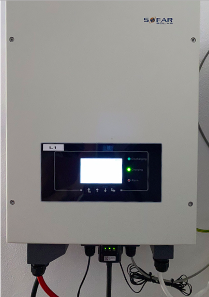
Sofar ME3000SP Inverter

I had never previously changed the firmware which was 2.40 but have now been through the process on my inverters and documented it here to I can refer to it next time.

Step 0 – Did you freeze your CTs?

The firmware upgrade requires that you power down your inverter. You should ensure you have your CT settings frozen first – see this page for instructions (setting up CTs section).

Step 1 – Power down the inverter

Turn off the AC power to the inverter, pull the fused DC isolator if you have one or turn off your complete battery pile.

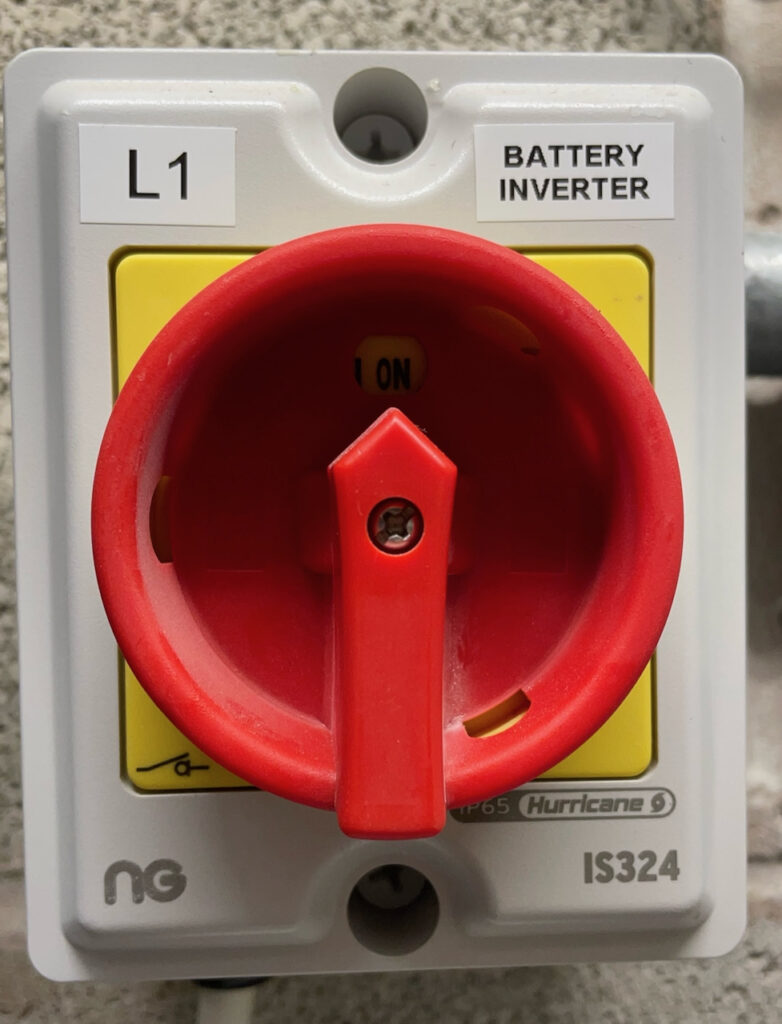
AC Isolator
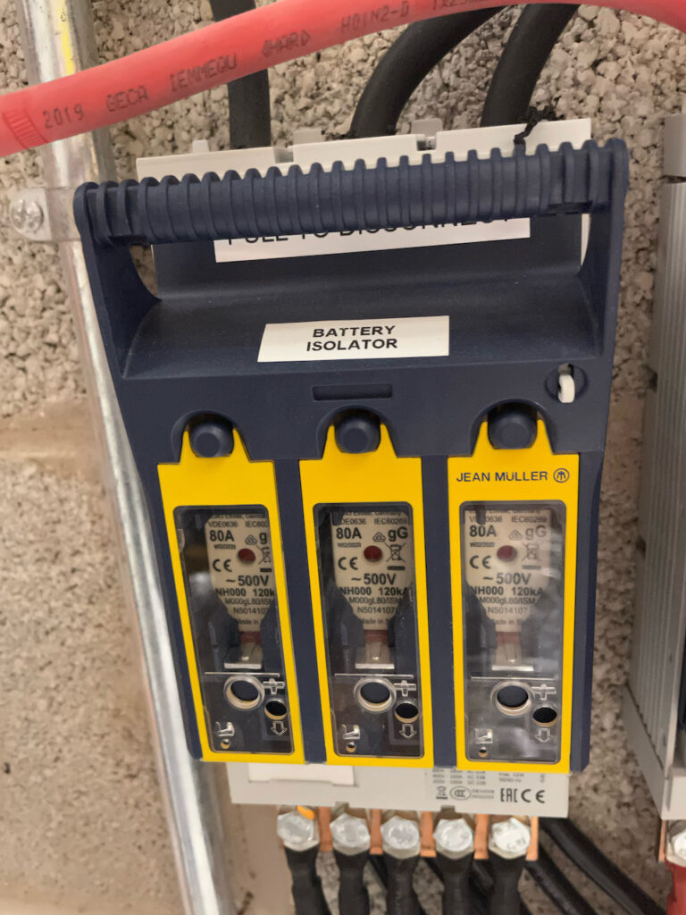
DC Fused Isolator

Step 2 – Remove communications cover

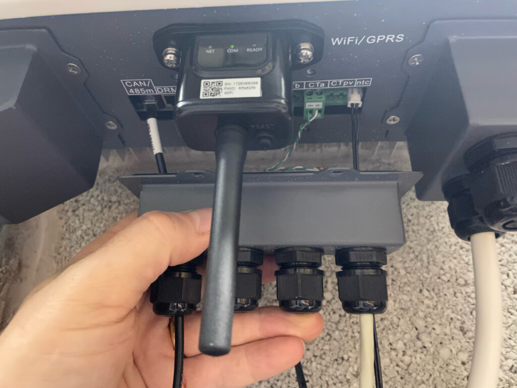
Remove the waterproof cover to the communications cables (loosen the glands first).

Remove the communications cover

Step 3 – Remove the microSD card

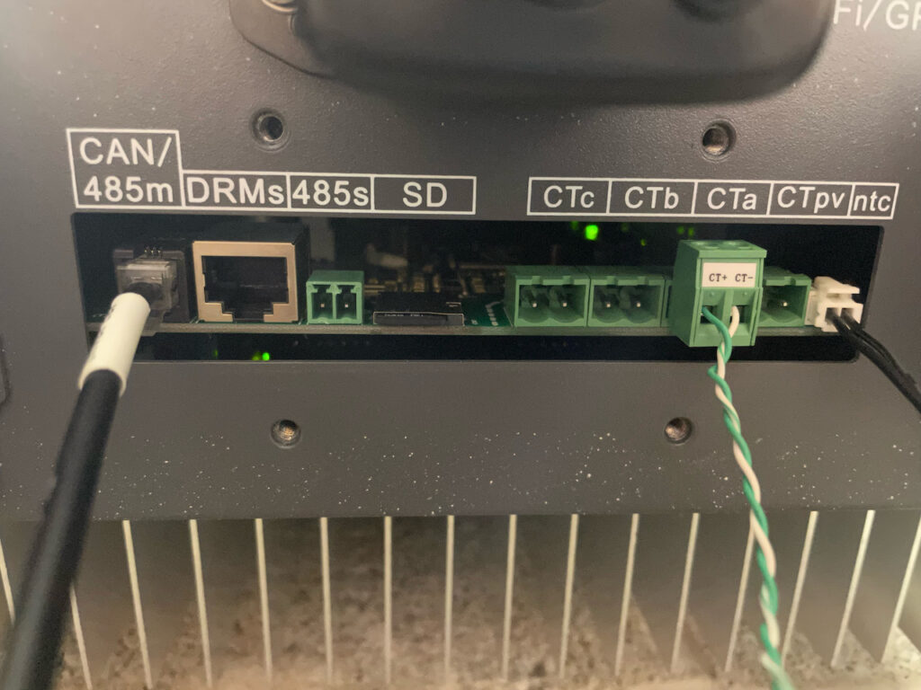
Inside the cover is the microSD card slot, which should have a card already in it. Press the card edge until it clicks. Release and it will then drop out of its slot enough so you can grab hold of it and withdraw it. The card is formatted MSDOS FAT32 and my card has CSV files on it with daily/monthly logging.

SD card location

Step 4 – Set up a new SD Card with the new firmware

Tim suggested in the comments that upgrading to 3.00+ firmware should be performed in 2 steps – first upgrade to 3.00 and then beyond. I thought I would give it a go straight to 3.06.. which worked fine.

Firmware file structure

To do this, you need to download the firmware from here and prepare the micro SD card. Unzip the appropriate firmware so you have an ES3000firmware folder with .bin files in it.

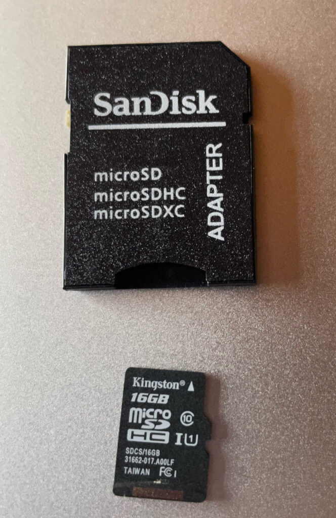
microSD card plus adapter

The microSD card needs to be formatted as MSDOS FAT32. Sofar instructions tell you to format the existing card, but I used another card which already came formatted that way. I used an adapter to plug it into my Macbook.

I copied the ES3000firmware folder to it and then inserted it into the card slot on the inverter (still powered down).

Next power the inverter back up. DC first, then wait 5 seconds then AC. It should boot as normal and then begin operation as if nothing had happened.

Step 5 – The actual upgrade

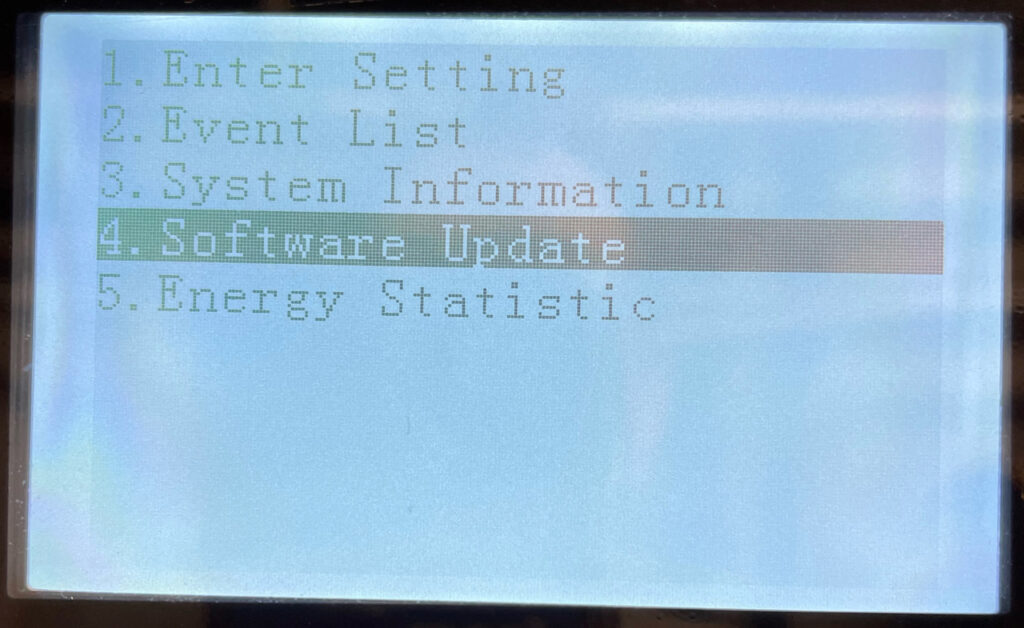
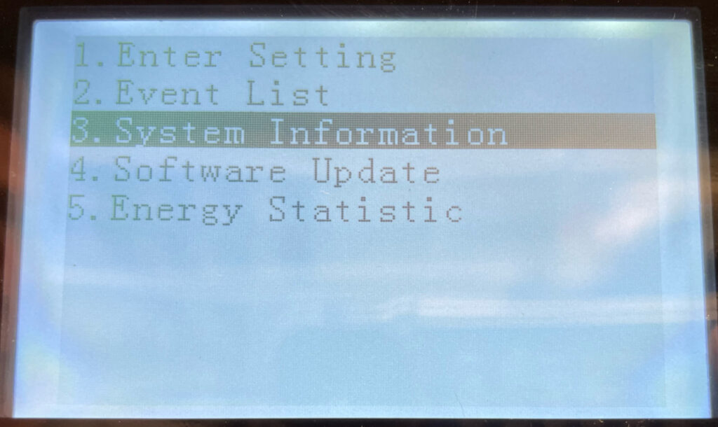
Use the back button to get the menu up, then select 4. Software Update.

Software Update

Press enter, then put in the password 0715.

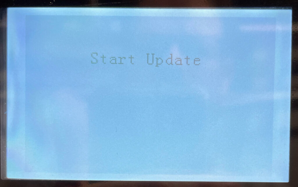
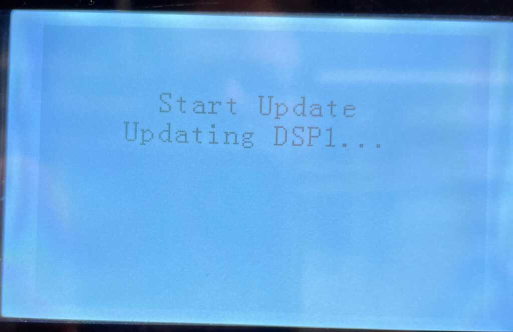
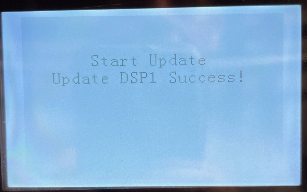
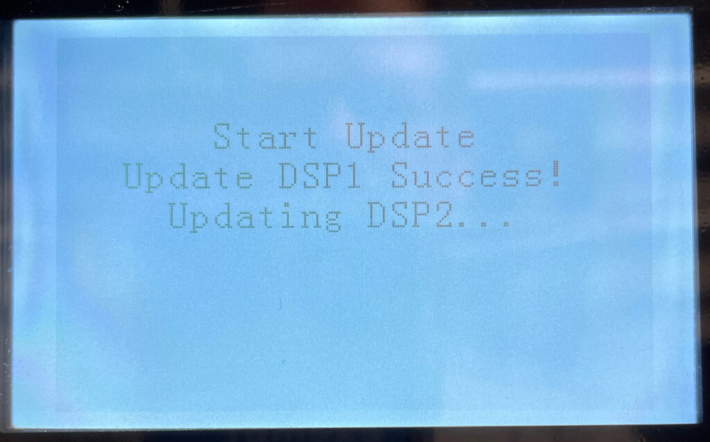
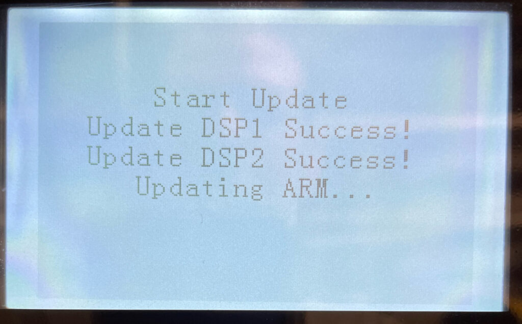
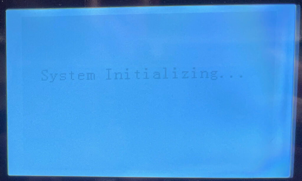
Here is the successful update sequence. Once the password has been correctly entered, you don’t need to do anything else.

Should really read ‘Update has started’
The update has finished.

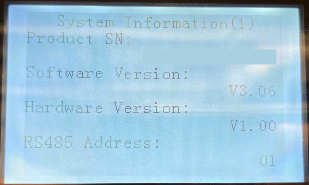
You can confirm the update worked:

System Information
Software version
Software version is now 3.06

Step 6 – Did it fail?

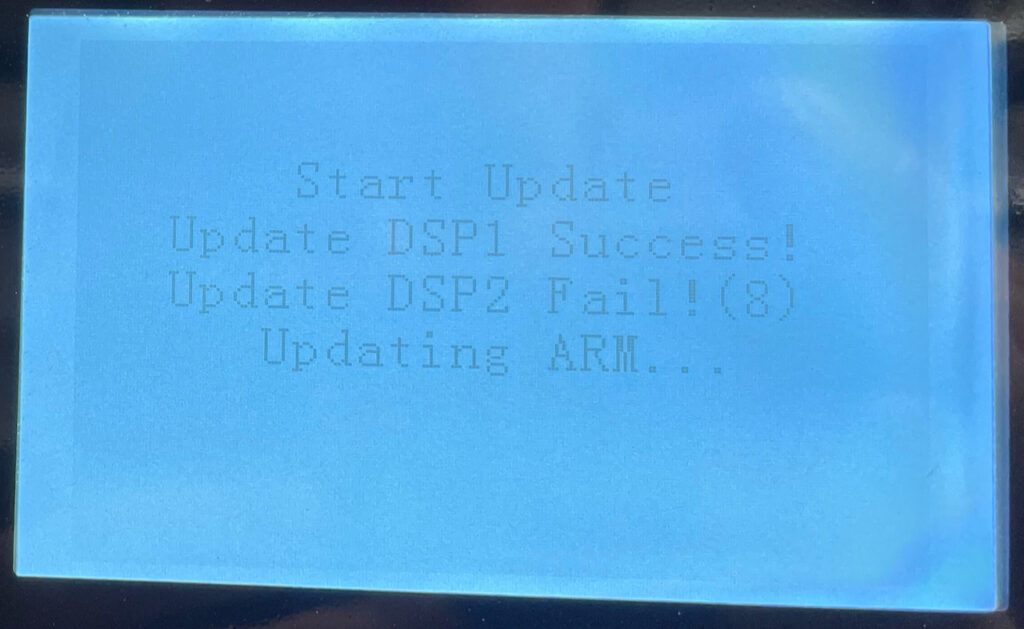
My success rate first time round was 1 out of 3. All my failures were on DPS2:

The update continues after DSP2 fails and the inverter reboots. However, the battery communications don’t work so this is not a satisfactory state to leave the inverter in.

If this happens, return to the start of Step 5 and try again.

Step 7 – Power down / replace card / restart

At this point, the inverter had started up and was operating normally. I then powered it down again, then swapped the microSD card for the original one. If you put the firmware on the original card, you wouldn’t need to do this. The Sofar instructions do say to power it down and restart though.

Successful update – new features

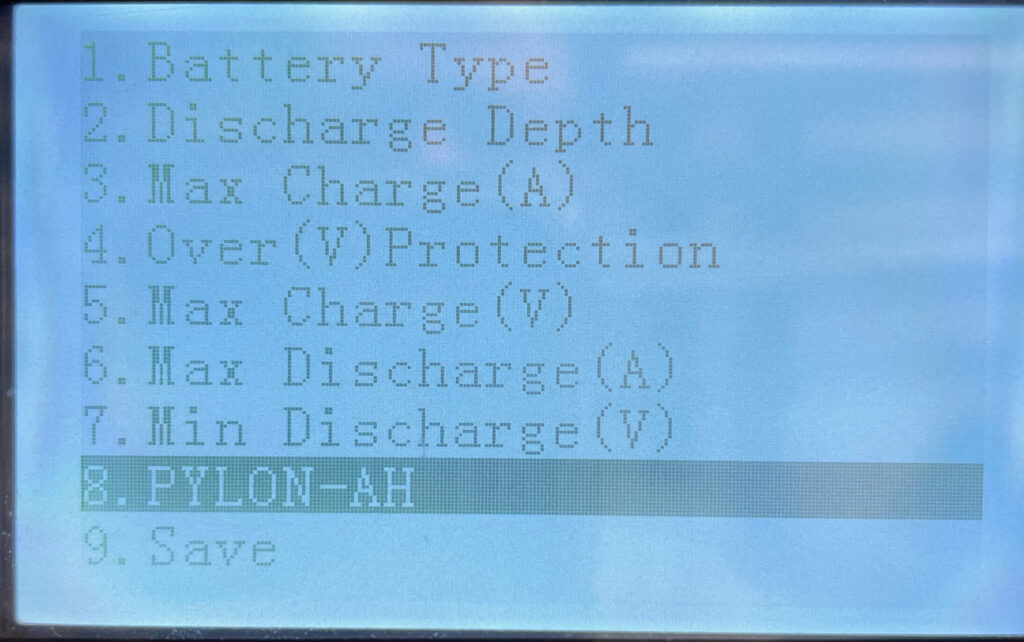
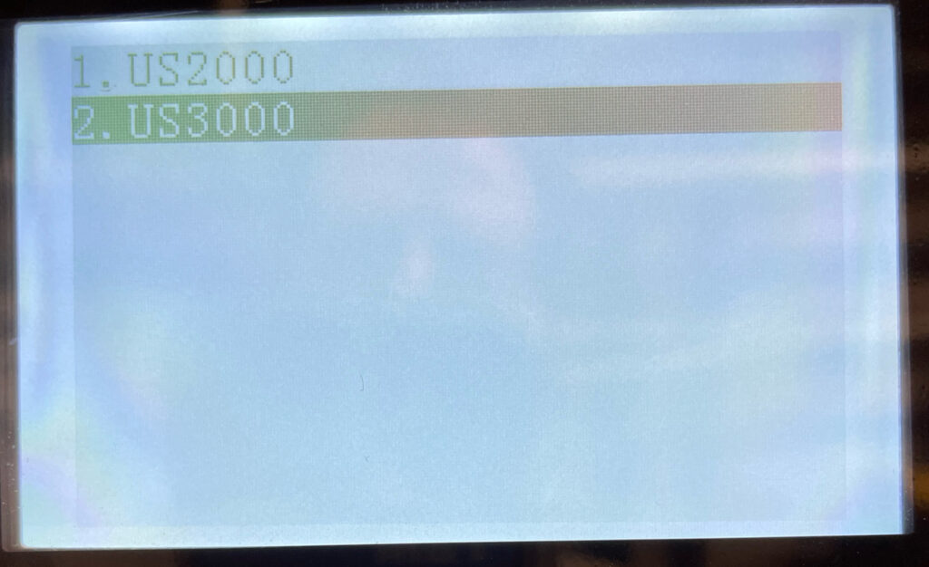
Moving from 2.40 to 3.06 gave me two new features – a new battery parameter with the ability to select US3000 batteries:

Battery parameter
US3000

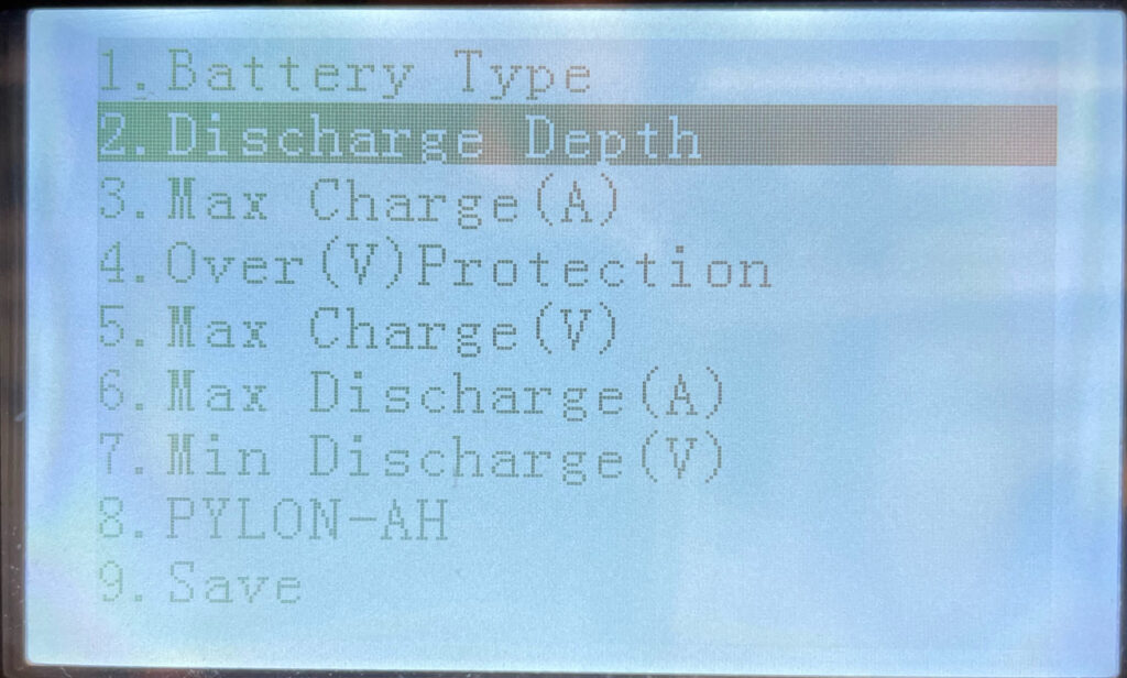
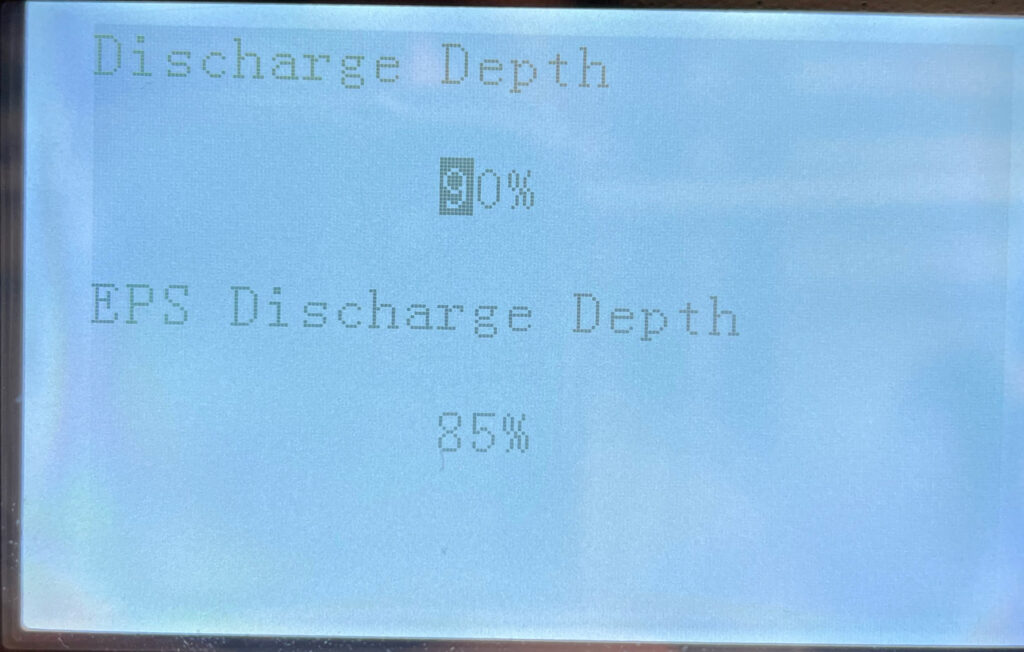
Plus depth of discharge now up to 90%:

Depth of Discharge
DOD 90%

Pylontech US2000 / US3000 CAN reading and CAN replication

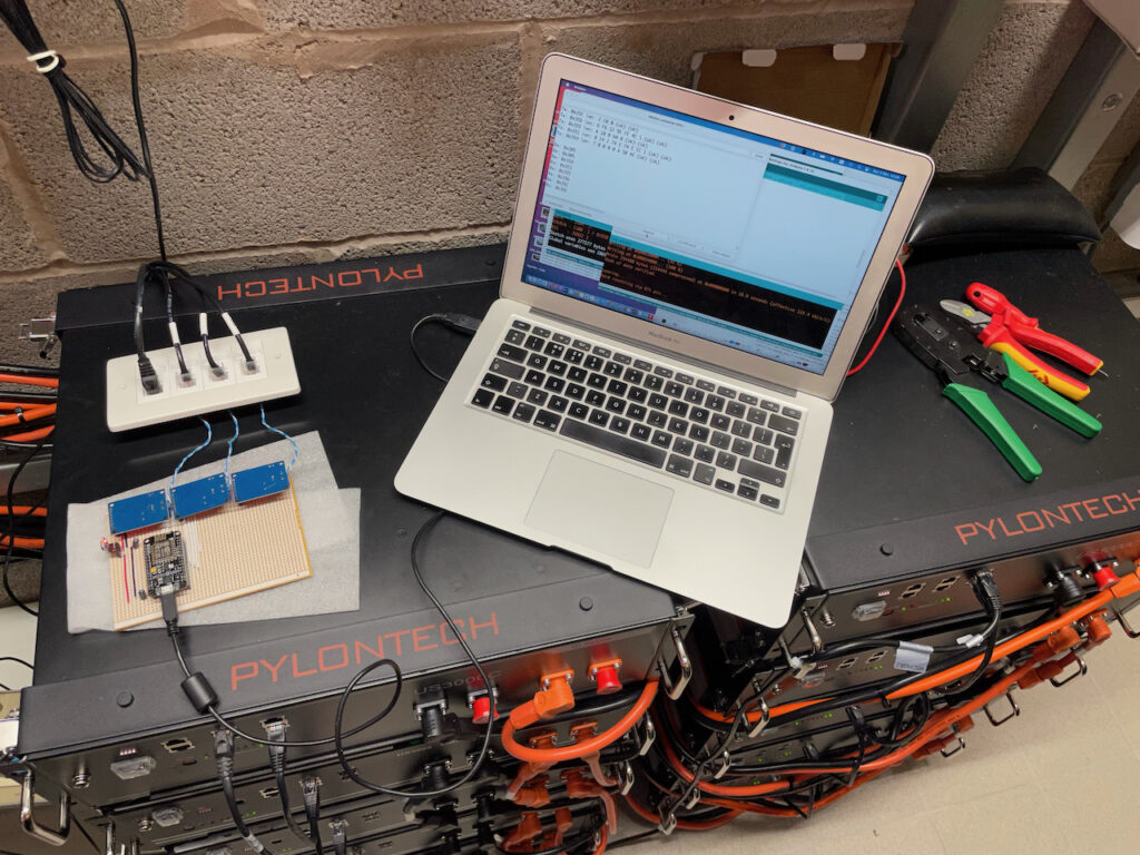
Following on from the previous post where I was able to read the CAN data, here is a sketch for the NodeMCU and MCP2515_CAN modules to collect the CAN data, interpret it, post it to emoncms, and also replicate it onto additional CAN busses for systems with multiple Sofar Solar ME3000SP inverter/chargers.

Pylontech CAN data reporting and replication

I had planned a simple sketch first, but reliably reading a complete set of CAN data proved less simple than I had imagined.

Catching all the CAN data

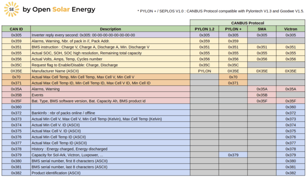
The Pylontech battery stack outputs its CAN data once per second. This consists of six CAN packets like this:

CAN ID – followed by 2 to 8 bytes of data:
0x351 – 14 02 74 0E 74 0E CC 01 – Battery voltage + current limits
0x355 – 1A 00 64 00 – State of Health (SOH) / State of Charge (SOC)
0x356 – 4e 13 02 03 04 05 – Voltage / Current / Temp
0x359 – 00 00 00 00 0A 50 4E – Protection & Alarm flags
0x35C – C0 00 – Battery charge request flags
0x35E – 50 59 4C 4F 4E 20 20 20 – Manufacturer name (“PYLON “)

If you are watching the bus, you will also see a 0x305 ID message which is output by the ME3000 once per second. The Pylontech data is sent fairly rapidly, and as was noted in the previous post, and is easy to loose. The MCP2515 has only two receive buffers and so can only hold two messages. If both buffers are full, any additional messages are ignored so the code must clear the buffers quickly during the stream of six messages from the batteries. The messages are always sent in the same order, and it is always the same messages which are lost if the code is too slow in checking. I suspect there are a couple which arrive very soon after the previous message is sent. The priority for the sketch is to collect and buffer the messages, and then process them less frequently.

Here is the first part of loop():

  // If CAN0_INT pin is low, read receive buffer
  if (!digitalRead(CAN0_INT)) {
    while ( CAN0.readMsgBuf(&rxId, &len, rxBuf) != CAN_NOMSG ) {
      store_can();
    }
  }

This is slightly different to the example code for the library (https://github.com/coryjfowler/MCP_CAN_lib/) which does only one check/read per loop() and was found to drop messages – and always the same IDs which the Pylontechs seem to deliver very soon after the previous message. The method above has been very reliable. The routine store_can() puts the CAN message in our own (larger) circular message buffer and does no post-processing – which would make it too slow. Prior to using this polling method in the main loop, I tried an interrupt routine to store to the buffer but this required a different library (which itself needed fixing) and caused new problems with clearing interrupt flags on the MCP2515 – resulting in more lost messages! Polling the interrupt pin on the MCP2515 has been the most reliable method I have found.

Buffering CAN Messages

It is important to buffer the CAN messages so we hold at least one full set of six representing the complete picture of the batteries via CAN. If we have the compete picture, we can pass it to emoncms for reporting. We can also relay it onto additional CAN buses for additional inverter/chargers. The sketch can also print the buffer to the serial port periodically so you can see what is happening (look for the setting INTERVAL_DISPLAY). Each line shows the buffer position, ID, 8 bytes of data, and 2x data length (first for emon post, second for bus replication):

7 35E 00 00 00 00 00 00 00 00 08 08
6 35C 00 00 00 00 00 00 00 00 08 08
5 356 00 00 00 00 0A 50 4E 00 07 07
4 355 14 02 74 0E 74 0E CC 01 08 08
3 351 0E 00 64 00 00 00 00 00 04 04
2 359 02 13 00 00 4A 01 00 00 06 06
1 305 C0 00 00 00 00 00 00 00 02 02
0 305 50 59 4C 4F 4E 20 20 20 08 08
31 35E 00 00 00 00 00 00 00 00 08 08
30 35C 00 00 00 00 00 00 00 00 08 08
29 356 00 00 00 00 0A 50 4E 00 07 00
28 355 14 02 74 0E 74 0E CC 01 08 00
27 351 0E 00 64 00 00 00 00 00 04 00
26 359 02 13 00 00 4A 01 00 00 06 00
25 305 C0 00 00 00 00 00 00 00 02 00
24 305 50 59 4C 4F 4E 20 20 20 08 00
23 35E 00 00 00 00 00 00 00 00 08 08
22 35C 00 00 00 00 00 00 00 00 08 08
21 356 00 00 00 00 0A 50 4E 00 07 07
20 355 14 02 74 0E 74 0E CC 01 08 08
19 351 0E 00 64 00 00 00 00 00 04 04
18 359 02 13 00 00 4A 01 00 00 06 06
17 305 C0 00 00 00 00 00 00 00 02 02
16 305 50 59 4C 4F 4E 20 20 20 08 08
15 35E 00 00 00 00 00 00 00 00 08 08
14 35C 00 00 00 00 00 00 00 00 08 08
13 356 00 00 00 00 0A 50 4E 00 07 07
12 355 14 02 74 0E 74 0E CC 01 08 08
11 351 0E 00 64 00 00 00 00 00 04 04
10 359 02 13 00 00 4A 01 00 00 06 06
9 305 C0 00 00 00 00 00 00 00 02 02
8 305 50 59 4C 4F 4E 20 20 20 08 08

Hardware

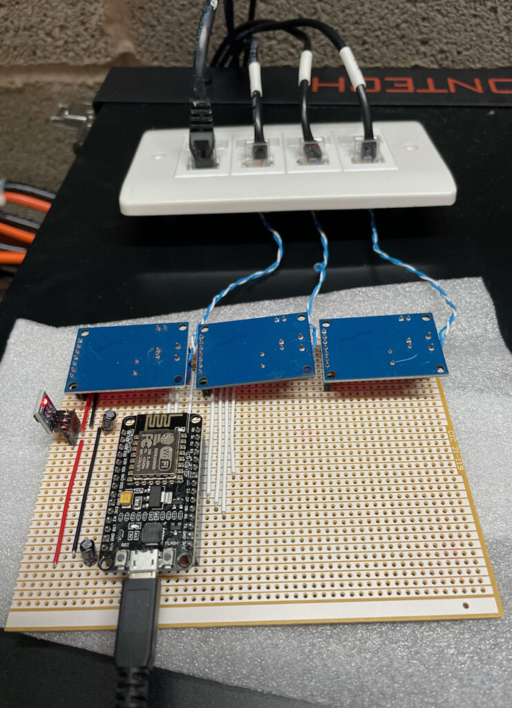
NodeMCU and MCP2515 CAN modules

The NodeMCU is connected to the 3x MCP2515_CAN modules in the same way as in the previous post. The only differences here are that the 3.3V supply to them is via a AMS1117-3.3 LDO 5v to 3.3V converter module which is fed from the 5V USB supply. I added 10uF 25V capacitors to the 5V and 3.3V output rails to ensure a stable supply (probably didn’t need these, but I considered it good practice). I am using I/O pins D1, D2, D3, D4 for CAN0 INT, CAN0 CS, CAN1 CS, CAN2 CS. D4 is best as a CS function rather than the INT as it is also used for UART communication during programming. The INT output on the MCP2515_CAN module would be pulled low if there was data on the CAN bus and this would interfere with programming if on an active CAN bus.

Some notes about the system and sketch

Firstly, messing around with your battery system is not a good idea unless you really, really, know what you are doing. You will most likely invalidate any warranties. You also risk:

  • destroying your battery system.
  • destroying your inverter/chargers.
  • burning your house down.
  • something worse.

YOU HAVE BEEN WARNED!

The connection to the first CAN bus for reading the data is done using the first CAN interface in listen-only mode and the CAN interface on the Pylontech batteries still connects to the first inverter. The interface also has no bus termination as this is provided at the two ends as usual – the battery, and the inverter. By connecting to the CAN bus this way, we ensure the first inverter is always connected to the batteries. This is important as it ensures the batteries always have a system looking after their interest – like making sure the charge never gets too low (the batteries can force the inverter to charge them from mains if they get too low).

There is one problem inherent in this connection method – the maximum charge and discharge currents are reported to the inverters as-is. This means there is the potential to over charge or over-discharge the batteries. For a small system, this could be a problem and should be considered. For example:

  • 2x US2000 batteries = 2x 20A = 40A maximum charge and discharge as reported by the batteries to the inverter.
  • if you have 3x inverters, each is sent 40A maximum charge/discharge setting.
  • Therefore theoretical maximum charge/discharge current at the batteries is 3x40A = 120A. BAD. You will need to manually reduce your maximum charge and discharge settings on each inverter.

However, if you have a stack of 10x US3000 batteries:

  • 10x US3000 batteries = 10x 37A = 370A charge and discharge as reported by the batteries to the inverter.
  • if you have 3x ME3000SP inverters, each is capable of 65A max. charge/discharge.
  • Total theoretical charge/discharge for the batteries is 3x 65A = 195A which is well within the 370A maximum.
  • Of course, your battery cabling needs to be up to the job:
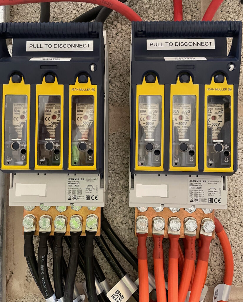
Battery protection
How to connect 10x Pylontech battery leads to 3x inverters. Terminal covers removed for photo!

The sketch

The sketch can be found here: https://github.com/setfirelabs/Pylontech_emoncms REMEMBER THE WARNINGS ABOVE BEFORE MESSING WITH YOUR SYSTEM!

The serial output should look something like this:

Ready
IP address: 192.168.1.115
Entering Configuration Mode Successful!
Setting Baudrate Successful!
Entering Configuration Mode Successful!
Setting Baudrate Successful!
Entering Configuration Mode Successful!
Setting Baudrate Successful!
Rx: 0x359
Rx: 0x351
Rx: 0x355
Rx: 0x356
Rx: 0x35C
Rx: 0x35E
Rx: 0x305
Rx: 0x305
Rx: 0x359
Rx: 0x351
Rx: 0x355
Rx: 0x356
Rx: 0x35C
Rx: 0x35E
Rx: 0x305
Rx: 0x305
Rx: 0x359
Rx: 0x351
Rx: 0x355
Rx: 0x356
Rx: 0x35C
Rx: 0x35E
Rx: 0x305

Tx: 0x35E len: 8 50 59 4C 4F 4E 20 20 20 (ok) (ok)
Tx: 0x35C len: 2 C0 0 (ok) (ok)
Tx: 0x356 len: 6 2 13 0 0 4A 1 (ok) (ok)
Tx: 0x355 len: 4 E 0 64 0 (ok) (ok)
Tx: 0x351 len: 8 14 2 74 E 74 E CC 1 (ok) (ok)
Tx: 0x359 len: 7 0 0 0 0 A 50 4E (ok) (ok)

..and have fun graphing!

emoncms pylontech graph

Multiple Sofar ME3000SP inverters for 3-phase setup?

(or multiple inverter/chargers connected to one battery pile)

Is it possible to connect multiple ME3000s to one (Pylontech) battery pile? The short answer is: yes, it is possible, but it doesn’t work all that well.

And don’t blame us if you damage your batteries / set fire to your house / etc. The use of this information is entirely at your own risk!

The US2000 / US3000 batteries talk to the Sofar Solar ME3000 inverter/charger using the CAN interface. Theoretically, once the first one inverter/charger is connected to the batteries using CAN and a battery setting of PYLON, any subsequent inverter/chargers can use a battery type of DEFAULT – which is generally used for lead-acid batteries.

Here are some rough battery parameters for the default battery type in this configuration:

  1. Battery type: DEFAULT
  2. Battery Capacity: (whatever your battery pile is)
  3. Discharge Depth: 80%
  4. Max Charge Current: (calculated as your battery capacity divided by number of ME3000s)
  5. Over Voltage Protection: 54.0V
  6. Max Charge Voltage: 51.5V (normally 52.8V but limited to stop over-voltage – see below)
  7. Max Discharge Current: (same as Max Charge Current)
  8. Low Voltage Protection: 45.9V
  9. Min Discharge Voltage: 49.0V (normally 47.2V but higher here to limit over-discharge)
  10. Empty Discharge Voltage: 46.7V
  11. Full Charge Voltage: 52.08V
  12. You also need to have the temperature probe connected (and ideally attached the to case of the top battery pack).

Limitations

Using these settings with a different battery technology poses a number of problems around the battery-protecting charging and discharging limits and also knowing the state of charge (SOC).

Voltage measurement

Knowing the voltage of the batteries is important since this is used by the inverter/charger to ensure the batteries are kept within their operating limits, which ensures they have a long and useful life.

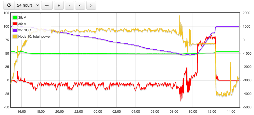
When using the DEFAULT battery setting, this voltage is measured inside the inverter, not inside the batteries. This causes a problem in that the more current is drawn from the batteries, the more the voltage drops due to cable and internal battery resistance. The boffins at Sofar Solar have thought of this though – and they compensate for it. However, they have no idea what the resistance of the cables is, and they think the battery is lead-acid. Have a look at this graph from an ME3000 in DEFAULT mode produced by Solarman covering a 24 hour period and showing SOC, Voltage and Current. The battery current is shown as red in the graph and starts the day at about zero. This is for phase L1.

Solarman Graph L1
Solarman Graph Using DEFAULT battery type – phase L1

Look at the two negative peaks at about 02:00 and 04:30. When the current is drawn, the voltage goes up! (Specifically, the first 26A draw causes a 1.1V increase, the second 30A draw causes a 1.2V increase.) A battery will not behave like this in real life – clearly the system is over-compensating for the resistance. This has a knock-on effect in our settings – we want to protect the batteries by stopping the voltage dropping too far when the SOC is low, which is done with the Minimum Discharge Voltage. For the PYLON type battery setting, this is minimum is 47.2V and so for DEFAULT we are using 49.0V to compensate in the settings above. This will be system-specific since it depends on battery size, likely current draw and battery cables.

The reverse can also be seen in the charging phase of the day – the voltage drops when charging and so is all over the place. Because during charging the voltage measurement is being artificially reduced, we need to compensate in the Maximum Charge Voltage by reducing it.

Compare the graph above to the inverter on the same battery pile using CAN for its readings over the same period. This is on L3:

Solarman using CAN
Solarman graph from ME3000 using CAN – phase L3

..the early current spike causes no change in the voltage and overall the voltage is far more stable.

State of Charge (SOC) calculations

OK – the inverter can see the battery, its voltage, knows the current being drawn or charged, and knows the capacity of the battery. However, it doesn’t know what any other inverter/chargers are doing and assumes it is the only one. Battery state of charge (SOC) is a calculated figure, whether the batteries are calculating and reporting it, or the inverter/charger is. In our case here, using the DEFAULT battery type, the inverter is attempting to work out the SOC. It only knows about itself, and so its calculations will not be accurate (whereas the battery management in the Pylontech batteries have the full picture).

You can see by comparing the graphs above that the SOC doesn’t look too different. The L3 graph is the accurate one, and the L1 one above shows a similar curve as the battery is charged. However, at the start of the graph (midnight) L1 shows the SOC too low, and after the battery pile is fully charged (15:30) it then remains too high.

Now for three graphs showing L1, L2, L3 on a different day.

The first graph shows L3 – which is connected via CAN to the batteries and shows the true picture:

Solarman graph - L3
Solarman graph – L3 – CAN connected to Pylontech battery pile.

SOC starts at 64% at midnight, dropping to 27% at 13:57 before starting to recharge, where it hits 72% at 18:13 before starting its discharge gain. Throughout the day the inverter is either discharging or charging the battery as the demand or excess on that phase requires. [Note that there is a display problem on the graph – the current scale is incorrect here – 0A is shown as about -15A.]

Here is L1 for the same day:

Solarman graph - L1
Solarman graph – L1 (DEFAULT battery type)

The SOC scale is different, but the day starts at 50%, drops to 36% at 10:04, but generally bears no resemblance to the actual SOC. The load on this phase is very constant. [Here the Solarman system is incorrectly reporting -6A when it should be zero.] Here is L2:

Solarman graph - L2
Solarman graph – L2 – DEFAULT battery type.

The day starts at 53%, drops to 42% at 03:38, recovers a bit and then starts climbing as charging starts at 11:50, reaching 78% at 18:39. The inverters don’t really have a clue what the SOC is, but seem to be periodically recalculating it based on the changing battery voltage.

Charge rates

For good battery management, charge rates vary depending on SOC. When eg. for LiFePO4 batteries, they are charged at 0.5C until they are close to their maximum charge (90%), then the charge rate is reduced to something like 0.2C. In order for the charger to reduce the charge rate at close to full charge, it needs to accurately know the state of charge.. which we have shown above is not the case with the DEFAULT setting.

Continuing to charge at 0.5C past 90% state of charge is likely to shorten the life of your batteries. But – the charge rate could already be limited by your charger. Each US2000 has a maximum charge rate of 20A and each US3000 a maximum charge of 37A; this is the 0.5C. We can therefore calculate the 0.2C which would be 8A for the US2000 and 14.8A for the US3000. Let’s say you had 10x US3000 – 0.2C would be 148A. If you had 3x ME3000s each set at 50A max charge, you would never exceed 0.2C anyway and so would be safe. If you had 4x US3000, 0.2C would be 4 x 14.8 = 59.2A so you should be more careful. As we have seen above, attempting to control the charge using the battery voltage is difficult because of software compensation of the voltage – during charging the voltage is suppressed. Of course, if your batteries tend not to get close to full charge, this is less of an issue. Also bear in mind that if you have 3x inverter/chargers, one will be connected via CAN and so you are only concerned with the other two. Maybe you can arrange them with your generating equipment so this is not a problem (eg. most generation on the one charger connected via CAN).