We have had a couple of ‘frisbees’ – the excellent Ubiquiti Unifi access points knocking around which were broken. Unusually, they run on 24V POE rather than the more common 48V. One of the minions here in the Labs didn’t realise this and tried to power them straight from a switch with 48V. They broke.

The symptoms were that the power supply light would only flash periodically in sync with an orange light in the device. Unplug the ethernet cable from the frisbee and the PSU light comes on solid. This says power supply is fine, frisbee is broken.
There is precious little information on these devices about fixing them, other than a few people who have done the same as us. The usual answer is ‘its broken – buy another’.
On opening the device (4x torx screws), there is no evidence of damage – no black marks, charring, exploded components to give any clues as to the failure.
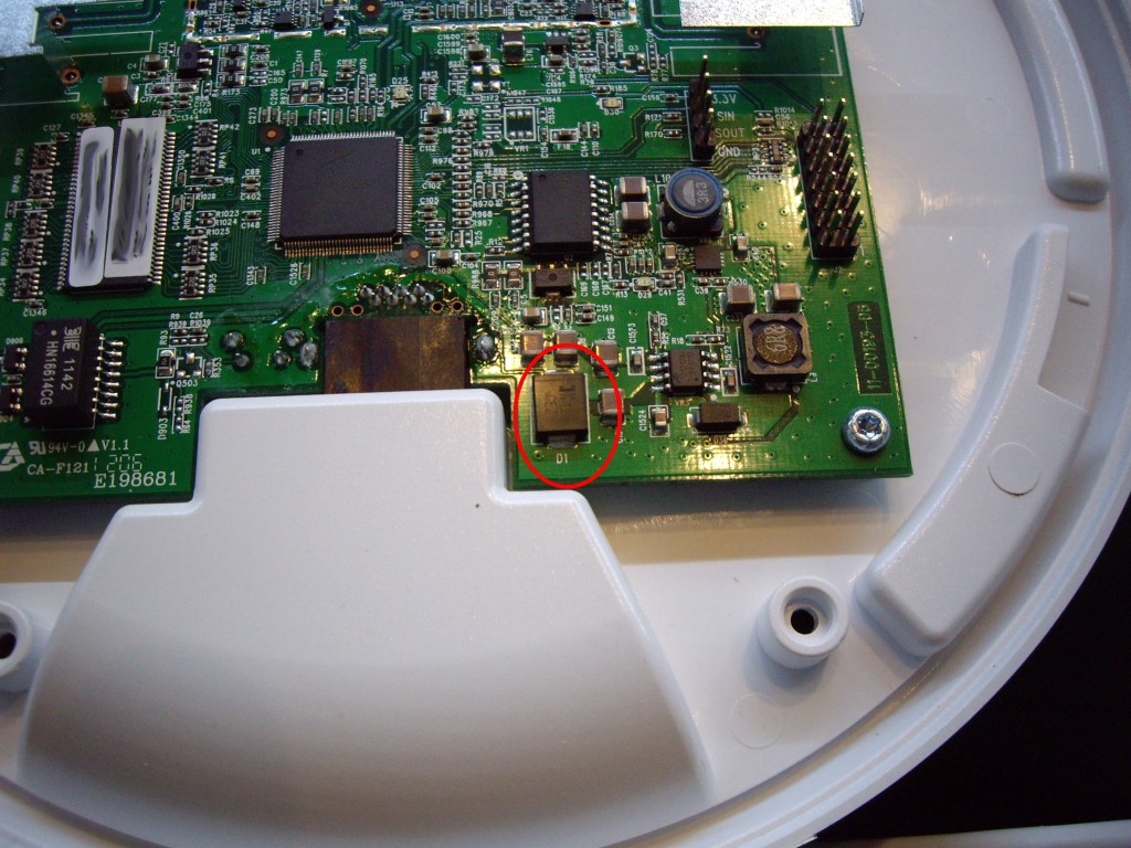
One comment I read talked about protection diodes which could be the cause. Looking at the circuit board, the power track from the ethernet connector goes to a voltage regulator chip, and on its way, there are some capacitors to ground and a large surface mount diode labelled ‘D1’. The markings on it are ‘129’ and ‘GEZ’. A little research shows this is a SMCJ24A which is a ‘transient voltage suppressor’ or TVS. GEZ is actually the identification of 24V working voltage rating used by Lite-On Semiconductor. This component is there to ‘clamp’ the voltage if it goes above 24V (actually somewhere between 26.7 and 29.5V) in order to protect the more sensitive circuits from voltage spikes (or people plugging in the wrong POE). In our case it had done its job in protecting the rest of the board, but has partially failed in that it won’t pass 24V for any length of time.
It is not too difficult to remove D1 using a soldering iron and some long nosed pliers. Plugging in the board with D1 removed shows it works, but D1 is there to protect from spikes and so it is a good idea to replace it. The component costs pence each and is available from RS Components here. When soldering it back in, make sure you get it the correct way round; there is a line on the top at one side – this goes away from the edge of the board – towards the top on the picture above.
Update:
We have two broken APs – with D1 removed, both of them light the LED D29 which indicates power, and both have 3.3V on the JTAG port. One of them shows network activity when the ethernet port is plugged into the network – LED D30 flashes, but the other does nothing else. Sometimes LED D25 (the yellow/green one) lights up orange when it is powered up, sometimes not. I think this one is definitely for the bin. The other one has a working boot loader. If you power it on whilst holding the reset button down, D25 goes green after about 5 seconds, and then cycles orange/green/off after 10+. I think it does need the BIOS reinstalling though..
For anyone following this, I suggest removing D1 (even by cutting it in two with side cutters) and then powering up. You can then assess the condition of the rest of the board before sourcing the replacement TVS. These things aren’t that expensive, so no point in wasting loads of time on it..
