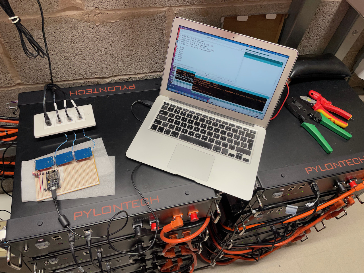
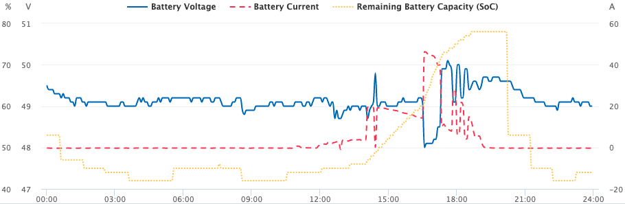
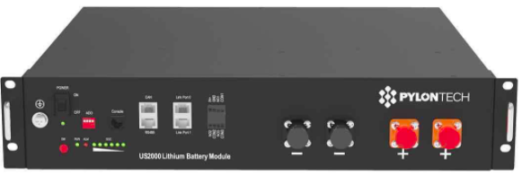
In the past few years, the CAN communication for Pylontech batteries have changed. Below are CAN outputs from some US5000s. These two different Pylontech batteries are connected together on the DC output, but as you can see, there are some slightly different numbers – the ‘old’ ones are reporting a different SOC, SOH etc:
Old Pylontechs:
ID: 351 Buffer: 14 2 C0 12 C0 12 C2 1   - Battery voltage + current limits
ID: 355 Buffer: 58 0 5E 0               - State of Health / State of Charge
ID: 356 Buffer: 7A 13 F2 FE 6B 1        - Voltage / Current / Temp
ID: 359 Buffer: 0 0 0 0 6 50 4E         - Protection & Alarms
ID: 35C Buffer: C0 0                    - Battery charge requests
ID: 35E Buffer: 50 59 4C 4F 4E 20 20 20 - "PYLON  "

New Pylontechs:
ID: 351 Buffer: 10 2 C0 12 C0 12 C2 1   - Battery voltage + current limits
ID: 355 Buffer: 54 0 60 0 0 0           - State of Health / State of Charge
ID: 356 Buffer: 7B 13 E9 FE 6B 1        - Voltage / Current / Temp
ID: 35A Buffer: 0 0 0 0 0 0 0 0         - NEW
ID: 35E Buffer: 50 59 4C 4F 4E 20 20 20 - "PYLON  "
ID: 35F Buffer: 4C 49 1 3 3C 2 AA 0     - NEW
We still have six CAN messages, but the ID 0x359 (Protection & Alarms) and 0x35C (charge/discharge requests) have gone, replaced by IDs 0x35A and 0x35F. Additionally, 0x355 has changed from 4 bytes to six. A bit of an explanation is on this table I found, produced by Open Solar Energy:
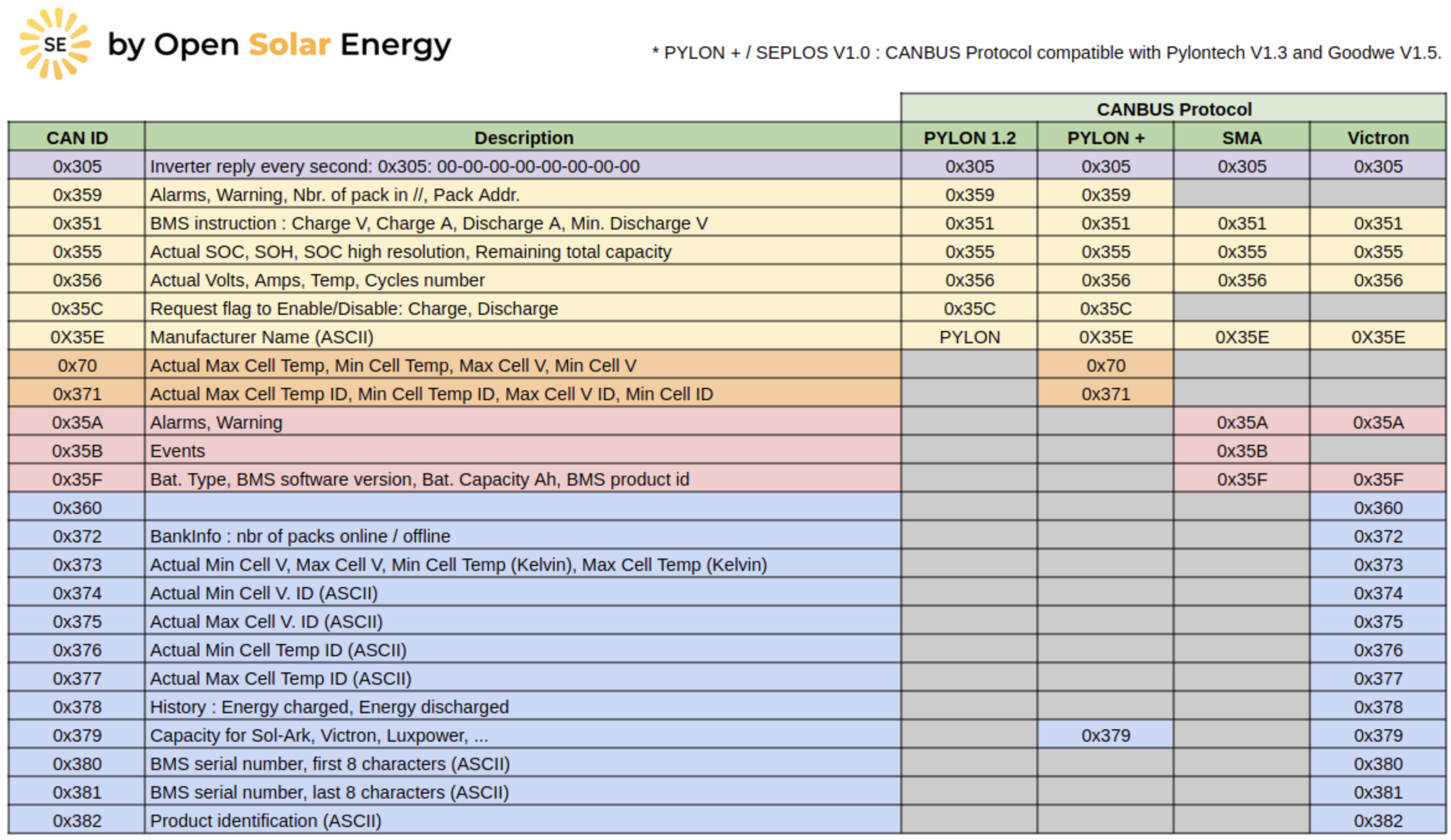
As you can see, 0x359 and 0x35C were unique to Pylon – not used by SMA and Victron. This would be a good reason to drop them – to bring things in line with other manufacturer’s protocols. 0x35A and 0x35F are both used by SMA and Victron.
So –
- 0x35A is ‘Alarms, Warnings’, replacing 0x359.
- 0x35F is ‘Battery type, BMS info’, replacing 0x35C.
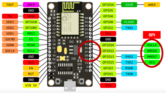
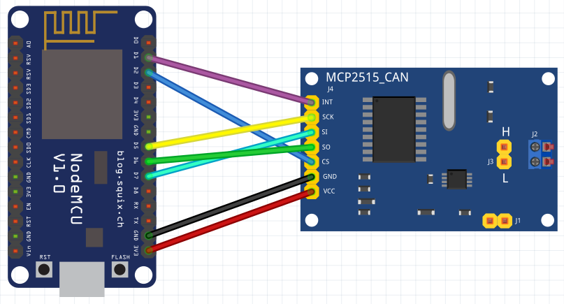
Now, let’s go through some code to translate from the CAN message. Here I am taking a CAN message already held in a buffer, hence the buf_pos reference. First 0x351..
unsigned int charge_v;
signed int charge_a;
signed int discharge_a;

charge_v = ((int)can_buffer[buf_pos][1] << 8) + ((int)can_buffer[buf_pos][0]);
charge_a = ((int)can_buffer[buf_pos][3] << 8) + ((int)can_buffer[buf_pos][2]);
if (charge_a > 0x7FFF) batt.charge_a = charge_a - 0x10000;
discharge_a = ((int)can_buffer[buf_pos][5] << 8) + ((int)can_buffer[buf_pos][4]);
if (discharge_a > 0x7FFF) discharge_a = discharge_a - 0x10000;
Note that 0x351 has 8 bytes not 6 – the Pylontech 1.2 protocol document gives no clues as to what the last two bytes are, however, if it is unsigned, then C2 01 gives 450 – or 45.0 x10 – looks like a low voltage threshold. SMA documentation confirms this as ‘Battery discharge voltage’ being the lower voltage limit allowed during discharge. So, we can add:
unsigned int discharge_v;
discharge_v = ((int)can_buffer[buf_pos][7] << 8) + ((int)can_buffer[buf_pos][6]);
Now 0x355..
unsigned int soh;
unsigned int soc;

soc = ((int)can_buffer[buf_pos][1] << 8) + ((int)can_buffer[buf_pos][0]);
soh = ((int)can_buffer[buf_pos][3] << 8) + ((int)can_buffer[buf_pos][2]);
Now 0x356..
signed int volts;
signed int current;
signed int temp;

volts = ((int)can_buffer[buf_pos][1] << 8) + ((int)can_buffer[buf_pos][0]);
if (volts > 0x7FFF) volts = volts - 0x10000;

current = ((int)can_buffer[buf_pos][3] << 8) + ((int)can_buffer[buf_pos][2]);
if (current > 0x7FFF) current = current - 0x10000;

temp = ((int)can_buffer[buf_pos][5] << 8) + ((int)can_buffer[buf_pos][4]);
if (temp > 0x7FFF) temp = temp - 0x10000;
Now 0x359 – Protection / Alarm Flags. Ok, I am being lazy here and not separating them out. But then this is dropped for V1.3..
byte pa_flags[4];

pa_flags[0] = can_buffer[buf_pos][0];
pa_flags[1] = can_buffer[buf_pos][1];
pa_flags[2] = can_buffer[buf_pos][2];
pa_flags[3] = can_buffer[buf_pos][3];

// Currently 14 flags:
// Protocol version 1.2 2018/04/08
//
// byte 0 : Protection
//  bit 7: Discharge overcurrent    PDO
//  bit 4: Cell undertemp           PUT
//  bit 3: Cell overtemp            POT
//  bit 2: Cell/module undervolt    PUV
//  bit 1: Cell/module overvolt     POV
// byte 1 : Protection
//  bit 3: System error             PSE
//  bit 0: Charge overcurrent       PCO
// byte 2 : Alarm
//  bit 7: Discharge highcurrent    ADH
//  bit 4: Cell lowtemp             ALT
//  bit 3: Cell hightemp            AHT
//  bit 2: Cell/module lowvolt      ALV
//  bit 1: Cell/module highvolt     AHV
// btye 3 : Alarm
//  bit 3: Internal comms fail      ACF
//  bit 0: Charge highcurrent       ACH
// byte 4: Module numbers - 8 bits unsigned - what is this? (ignoring)
0x35A – New for V1.3 – Alarms. Fortunately, SMA publish this.
byte pa_flags[4];

pa_flags[0] = can_buffer[buf_pos][0];
pa_flags[1] = can_buffer[buf_pos][1];
pa_flags[2] = can_buffer[buf_pos][2];
pa_flags[3] = can_buffer[buf_pos][3];

// byte 0
//  bit 7 - high temp alarm clears
//  bit 6 - high temp alarm
//  bit 5 - low voltage alarm clears
//  bit 4 - low voltage alarm
//  bit 3 - high voltage alarm clears
//  bit 2 - high voltage alarm
//  bit 1 - general alarm clears
//  bit 0 - general alarm

// byte 1
//  bit 7 - high current alarm clears
//  bit 6 - high current alarm
//  bit 5 - low temp charge alarm clears
//  bit 4 - low temp charge alarm
//  bit 3 - high temp charge alarm clears
//  bit 2 - high temp charge alarm
//  bit 1 - low temp alarm clears
//  bit 0 - low temp alarm

// byte 2
//  bit 7 - BMS internal fault clears
//  bit 6 - BMS internal fault
//  bit 5 - short circuit fault clears
//  bit 4 - short circuit fault
//  bit 3 - contactor fault clears
//  bit 2 - contactor fault
//  bit 1 - high current charge alarm clears
//  bit 0 - high current charge alarm (charge current too high)

// byte 3 - NOT FOR EXTERNAL USE
// byte 4 - SEEMS TO BE DUPLICATE OF BYTE 0
// byte 5 - SEEMS TO BE DUPLICATE OF BYTE 1
// byte 6 - SEEMS TO BE DUPLICATE OF BYTE 2
// byte 7
//  bit 1 - cell imbalance clears
//  bit 0 - cell imbalance
0x35C – V1.2 Battery charge requests / charge, discharge enable.
byte req_flags;
bool charge_enable = false;
bool discharge_enable = false;
bool request_force_charge1 = false;
bool request_force_charge2 = false;
bool request_full_charge = false;
bool force_bypass = false;
req_flags = can_buffer[buf_pos][0];

// Request flags (0x35C)
//  byte 0: Request flags
//   bit 3: Request full charge     RFC
//   bit 4: Request force charge 2  RF2
//   bit 5: Request force charge 1  RF1
//   bit 6: Discharge enable        RDE
//   bit 7: Charge enable           RCE

request_full_charge = (can_buffer[buf_pos][0] & 0x08);
request_force_charge2 = (can_buffer[buf_pos][0] & 0x10);
request_force_charge1 = (can_buffer[buf_pos][0] & 0x20);
discharge_enable = (can_buffer[buf_pos][0] & 0x40);
charge_enable = (can_buffer[buf_pos][0] & 0x80);
0x35F – V1.3 Battery information
// 0x35F - 4C 49 01 03 3C 02 AA 00
// Byte 0,1 - Battery type
// Byte 2,3 - BMS Version
// Byte 4,5 - Battery Capacity Ah (x10)
// Byte 6,7 - (reserved) Manufacturer ID

unsigned int type;
unsigned int bms_version;
unsigned int capacity;
unsigned int manufacturer_id;

type = ((int)can_buffer[buf_pos][1] << 8) + ((int)can_buffer[buf_pos][0]);
bms_version = ((int)can_buffer[buf_pos][3] << 8) + ((int)can_buffer[buf_pos][2]);
capacity = ((int)can_buffer[buf_pos][5] << 8) + ((int)can_buffer[buf_pos][4]);
manufacturer_id = ((int)can_buffer[buf_pos][7] << 8) + ((int)can_buffer[buf_pos][6]);
Loss of 0x35C
It’s a shame that the 0x35C CAN frame is no longer used. This could provide a great way to control the charging where it is difficult to do it directly on the inverter. For example, the SMA Sunny Islands are controlled via the Sunny Home Manager, which itself is controlled via the Sunny Portal. This is not ideal where you want your home automation system to do the work. Being able to leave the Sunny Island in zero export mode for example, but then force an overnight charge via 0x35C frames would be handy.
Next job – text whether the 0x35C frame is still obeyed..

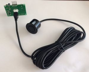 The serial-output of the DYP-ME007Y ultrasonic range detector is pretty good when you are measuring the distance to a static object with little or no other obstacles creating ‘noise’.