Category Archives: Building Automation

Pylontech US2000/US3000 NodeMCU CAN reader

The Pylontech batteries use either CAN or RS485 to communicate with the inverter. This post is a look at the CAN interface, and how to read that information to allow output to something like emoncms or MQTT.

Pylontech US2000 Battery
Pylontech US2000

Battery communication via the CAN interface is used by the Sofar Solar ME3000 inverter/charger in the setup we have and so the information here is based on this.

There is a Pylontech document specifying the CAN communications around on the internet although it is not that easy to find, and people connected with or in communication with Pylontech seem reluctant to share is, I think because of a NDA. It is, however, out there and if you know what to search for you can find it (ahem, CAN Bus Protocol Pylon low voltage).

The data is output by the battery (or master of a connected battery stack) every 1 second. The data rate is 500kbps and the output information is:

  • Protection Flags (eg. over/under temp)
  • Alarm Flags (eg. over current / voltage, communication fail)
  • Request Flags (eg. force charge)
  • State of Charge and State of Health
  • Voltage, current, Temperature
  • Maximum Voltage, Maximum charge current, Maximum discharge current

The information is for a complete pile (stack of batteries) basis and so there is no information on individual cells, for example.

Reading CAN

Since the CAN bus is a bus (!), multiple communicators can be connected to it. The Pylontech and the ME3000 inverter are the two end-points as they have the resistor terminators. This means another CAN device on the same must be unterminated. (So you can’t for example connect another ME3000 to it and expect it to work.) You can connect into the bus with an unterminated device and read the data without interfering with it. THIS IS GOOD because there is important battery management stuff going on between the inverter/charger and the batteries which you SHOULD NOT MEDDLE WITH. For example, The battery will force a charge from the inverter if it is at a very low state of charge, or if it thinks the state of charge is inaccurate (due to not having reached full charge for a while). Ultimately, you don’t want dead batteries, or a fire on your hands.

MCP2515_CAN Module
MCP2515_CAN Module

The MCP2515_CAN module is a CAN interface which communicates with the NodeMCU via SPI. It can also be powered from 5V or (in our case) 3.3V. J1 is for enabling the terminator resistor so we leave it unconnected. J2 is for the connection to the CAN bus.

SPI (Serial Peripheral Interface) uses four wires for communication. It is a full-duplex, master-slave interface where only one peripheral can communicate with the master at one time. However, multiple peripherals can be connected – and then a fifth wire is used to select which device to talk to – CS or ‘Chip Select’. 

In addition, an interrupt line can be used for the peripheral to signal that there is something to read from it.

The NodeMCU has two SPI interfaces (SPI and HSPI) built-in to the hardware, but one is used internally (SPI – for flash) and so we use the other – HSPI. This is specified here: https://nodemcu.readthedocs.io/en/release/modules/spi/

On the NodeMCU V0.9 board, the useable SPI interface was labelled:

NodeMCU V0.9
NodeMCU V0.9 Pinout

But on the V1.0, only the D lines are labelled:

NodeMCU V1.0 SPI Interface

They are both in the same place though. Here are the assignments:

SignalIO indexESP8266 pin
HSPI CLKD5GPIO14
HSPI /CSD8GPIO15
HSPI MOSID7GPIO13
HSPI MISOD6GPIO12

We are using the NodeMCU as the SPI Master device, so MOSI becomes Master Out and MISO becomes Master In.

MCP2515_CAN J4:

  • INT – interrupt
  • SCK – Serial Clock
  • SI – Slave In
  • SO – Slave Out
  • CS – Chip Select
  • GND – Ground power connection
  • VCC – + Volts connection

We connect the Master Out on the NodeMCU to Slave In and Master In to Slave out:

NodeMCU to MCP2515_CAN module

Powering the interface module

Now, the MCP2515_CAN requires that its power supply matches the voltage of the communicating device. With NodeMCU we are running at 3.3V and so the MCP2515_CAN can also be powered from 3.3V. 

HOWEVER, with the NodeMCU board  powered via the USB connector it is creating its own 3.3V via an on-board regulator from the 5V USB input. This is not sufficient to power the MCP2515_CAN for transmissions on the CAN bus. It is enough for just reading the bus though and so you can see we have powered the board from a 3.3V pin on the NodeMCU. (If you needed more power then a step-down module such as the AMS1117-3.3 LDO module could be connected to the 5V pin to provide the 3.3V for the MCP2515_CAN.

Connecting to the CAN bus

The CAN bus connector on the Pylontech battery is an RJ45 connector – the same as used for networking. CAN uses two wires and these are the blue pair – the centre two pins of the connector. To connect into the bus, we can use a pair of RJ45 sockets connected together with the pair connected to our CAN input:

CAN RJ45 connections

All hardware is now ready! It can be tested using the coryjfowler library https://github.com/coryjfowler/MCP_CAN_lib and the example sketch CAN_receive.ino with the CS and INT data pins set to match ours:

#define CAN0_INT D1
MCP_CAN CAN0(D2);

Now look for the line: if(CAN0.begin(MCP_ANY, CAN_500KBPS, MCP_16MHZ) == CAN_OK) and if you have an 8MHz crystal on your MCP2515_CAN module, change it to:

if(CAN0.begin(MCP_ANY, CAN_500KBPS, MCP_8HZ) == CAN_OK)

Connecting into to the CAN bus with an RJ45 cable from the top battery CAN port to our RJ45 socket, and then connecting the inverter comms cable to the other RJ45 puts us on the CAN bus, and so the sketch can be uploaded and run. If you have been successful, you should get some CAN data in your serial monitor like:

Standard ID: 0x305       DLC: 8  Data: 0x00 0x00 0x00 0x00 0x00 0x00 0x00 0x00
Standard ID: 0x35E       DLC: 8  Data: 0x50 0x59 0x4C 0x4F 0x4E 0x20 0x20 0x20
Standard ID: 0x359       DLC: 7  Data: 0x00 0x00 0x00 0x00 0x04 0x50 0x4E
Standard ID: 0x305       DLC: 8  Data: 0x00 0x00 0x00 0x00 0x00 0x00 0x00 0x00
Standard ID: 0x359       DLC: 7  Data: 0x00 0x00 0x00 0x00 0x04 0x50 0x4E
Standard ID: 0x35E       DLC: 8  Data: 0x50 0x59 0x4C 0x4F 0x4E 0x20 0x20 0x20
Standard ID: 0x351       DLC: 8  Data: 0x14 0x02 0xC8 0x05 0xC8 0x05 0xCC 0x01
Standard ID: 0x305       DLC: 8  Data: 0x00 0x00 0x00 0x00 0x00 0x00 0x00 0x00
Standard ID: 0x35E       DLC: 8  Data: 0x50 0x59 0x4C 0x4F 0x4E 0x20 0x20 0x20
Standard ID: 0x359       DLC: 7  Data: 0x00 0x00 0x00 0x00 0x04 0x50 0x4E
Standard ID: 0x305       DLC: 8  Data: 0x00 0x00 0x00 0x00 0x00 0x00 0x00 0x00
Standard ID: 0x359       DLC: 7  Data: 0x00 0x00 0x00 0x00 0x04 0x50 0x4E
Standard ID: 0x35E       DLC: 8  Data: 0x50 0x59 0x4C 0x4F 0x4E 0x20 0x20 0x20
Standard ID: 0x351       DLC: 8  Data: 0x14 0x02 0xC8 0x05 0xC8 0x05 0xCC 0x01
Standard ID: 0x305       DLC: 8  Data: 0x00 0x00 0x00 0x00 0x00 0x00 0x00 0x00
Standard ID: 0x35E       DLC: 8  Data: 0x50 0x59 0x4C 0x4F 0x4E 0x20 0x20 0x20
Standard ID: 0x359       DLC: 7  Data: 0x00 0x00 0x00 0x00 0x04 0x50 0x4E

A couple of things to point out here: outputting all this junk to the serial port is causing some packets to be missed – the loop is too slow and the CAN buffer is not cleared in time to receive them all (eg. there is no 0x35C ID here) and also the CAN_receive.ino sketch puts our CAN interface into MCP_NORMAL mode – which sends ACKs (we should really be in CAN_LISTEN mode).

Next post – a sketch to decode this data and send it somewhere useful..

Update – post is here: Complete sketch for reading and posting the Pylontech CAN data to emoncms, plus replication to additional CAN busses.

Sofar Solar ME3000SP Battery Inverters – installation tips

Sofar ME3000SP Inverter

Some useful things about this inverter which are not mentioned, or not obvious from the manual. This is based on experience with software version 2.4.

Connecting things up

You will need a replacement 20mm cable gland for the mains connection(s) if you are using a 3-core flex as the bung in each cable gland has 3x small holes and so expects 3x single core cables.

Mains cable gland

The unit comes with 2x M6 cable lugs for 25sqmm DC cables but M8 lugs fit fine (eg. on the end of the Pylontech cables).

Setting up the CTs

The unit comes with 2x CT clamps:

CT clamp

One is for the supply and should be clipped on to your incoming supply live (big fat single-core cable next to your meter). The other is to monitor your generation and so clips to the live wire supply to your PV panels (inside your generation board etc.).

The setup procedure for your inverter includes the steps:

  1. Make sure all PV is off.
  2. Turn on battery supply to inverter.
  3. Turn on mains supply to inverter.
  4. (now set up time/grid profile/battery)
  5. Make sure you are consuming at least 200W.
  6. Turn on the PV and watch it on the display.

What has actually happened here is that the system has worked out which way round the current clamps are (remember you didn’t have to install them a particular way round?)

Now the important part: if you switch off and restart the system, it will go through the same CT configuration again. In fact, there appear to be a number of ‘events’ which cause the CT reconfig:

  • Mains off/on
  • Battery off/on
  • Change work mode

That means that if you cause the CT reconfig when you are exporting power, it will incorrectly read this as an import and then start exporting until it reaches maximum export. Imagine you are currently exporting 2.5kW from your PV – this then ramps up to 2.5kW plus another 3kW from the inverter = 5.5kW export! You do have a G99 relay to stop this don’t you?!?

There is a way round this though: FREEZE CT. This is something you should do when you are happy it is configured correctly. Go to Configuration, then down to option 13:

13 - CT configuration

Enter the password:

Enter password

You will see the CTs, and at the bottom ‘UNFREEZE’ (which counter-intuitively means ‘CTs not frozen’:

CT Unfreeze

Press the down button to display ‘FREEZE’:

CT Freeze

..and then press ‘enter’ to save (then enter again to get off the confirmation screen). You can check the CT direction is frozen from System Information, screen 4:

System Information

..which should now show ‘Frozen’:

System Information 4

CTpv isn’t needed

It is possible to use this inverter without the pv sensor. It appears the CTa clamp is the only one used for import/export. This is good news for people who are not able to monitor all (or any) of their generation due to it being connected into different parts of the mains system without a central point for a CT. Obviously you won’t get logged data for the generation and various totals will not be accurate on the system.

Datalogger

The inverter comes with a datalogger with WiFi. This is something not mentioned in the manual for the inverter. It connects to a DB9 port on the bottom of the unit and once you have it connected to your wifi network, it posts the unit’s data to the Solarman cloud-based system.

Datalogger

Pylontech US3000 and battery capacity

The inverter doesn’t seem to be able to tell the difference between the US2000 and US3000 on the CAN bus at the moment and so incorrectly sets the capacity to 50Ah per battery instead of 75Ah for the larger US3000.

Changing battery settings

Beware: In order to change battery settings, you have to start by selecting the battery type – at this point, the defaults are loaded, overwriting whatever tweaks you previously made. Make sure you go through each parameter again!

Ultrasonic range measurement for tank level – good idea or not?

Not. I have found it impossible to get good, consistent and reliable readings from an ultrasonic based system used to monitor a water tank . Reasons include:

  • spurious results reported by the hardware
  • anything causing reflections above the water level interferes with what should be the stronger reflection from the actual water.
  • Spider webs!
  • Stillage tube with condensation on the inside
  • Stillage tube crud inside at high-water mark

..so to conclude, next step is to come up with a capacitance based measuring device. Watch this space.

Dealing with DYP-ME007Y TX spurious readings

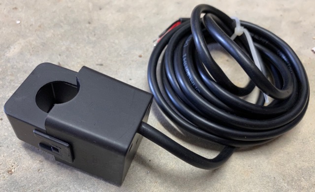
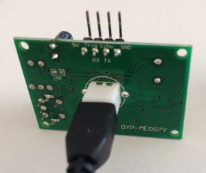
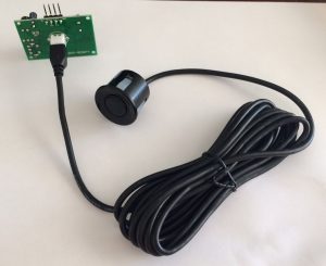
The serial-output of the DYP-ME007Y ultrasonic range detector is pretty good when you are measuring the distance to a static object with little or no other obstacles creating ‘noise’.

However, the odd spurious reading does crop in from time to time. For example:

201cm
201cm
201cm
128cm
201cm
201cm
201cm
201cm
201cm
201cm

This is actual data, and the spurious 128cm makes no sense and needs to be ignored (rather than just taking an average). Fortunately, @JMMS-Karunarathne and @MikeMeinz wrote some code to correct for this here: https://www.codeproject.com/tips/813946/a-method-to-ignore-anomalies-in-an-ultrasonic-dist

The code takes a group of samples and counts how many of each there are. It then picks the measurement with the highest count (the ‘mode’). In the above example, there are 9 counts of 201cm – which would be returned as the measurement.

So far, so good..

However, there is a problem where all the data is rubbish. Look at this actual data:

275cm
273cm
273cm
275cm
0cm
483cm
0cm
0cm
125cm
235cm
274cm
274cm
274cm
690cm
816cm
274cm
274cm
273cm
0cm
483cm
0cm
274cm
274cm
90cm
184cm
292cm
273cm
539cm
648cm
316cm

This was produced by out-of-range measurements – the object was less than 28cm from the sensor. The measurement which occurred the most was 274cm and so the algorithm would return this seemingly meaningful result.

An improvement to the ‘mode’ routine would be to apply a ‘confidence’ to the measurement. In my code, I take 30 readings, and require a minimum of 20 of the same to accept it as a good measurement. I try this five times over, after which the routine gives up and returns a zero indicating out-of-range. This seems to work well.

Except some of the time. This looks like good data:

82cm
82cm
82cm
82cm
83cm
82cm
82cm
83cm
83cm
83cm
83cm
83cm
83cm
83cm
83cm
82cm
83cm
83cm
83cm
82cm
82cm
83cm
82cm
83cm
82cm
80cm
83cm
83cm
82cm
82cm
confidence was 16
Returning 0cm

Here 83cm was only measured 16 times. This was an absolutely static measurement on the bench, however the returned value was either 82 or 83cm (ignoring the 1x 80cm!).

The way to deal with this is to look at the readings +1 or -1 from the mode. If either the count of the mode, added to the count of the mode+1, or mode-1 adds up to at least the threshold, then the result is good.

UPDATE:

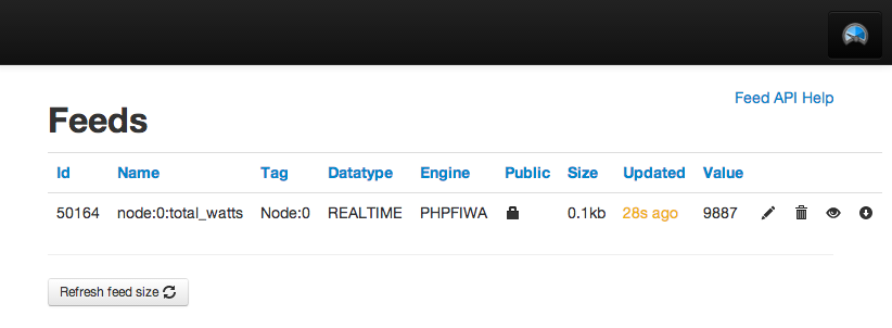
Here is my code to do all this and post the result to an emoncms system using an EPS8266. As you will see, I adapted code from https://www.codeproject.com/tips/813946/a-method-to-ignore-anomalies-in-an-ultrasonic-dist


/*
This sketch sends data via HTTP GET requests to emoncms.
Reads a DYP-ME007Y TX ultrasonic sensor to output distance
data to emoncms
*/

//uncomment this for dev mode
#define DEVMODE 1

// uncomment so disable sending a result when it is the same as the last one (power save etc.)
// #define NO_SEND_SAME 1

#include <ESP8266WiFi.h>
#include <SoftwareSerial.h>

// pin assignments. TX on the arduino connects to RX on the sensor, RX to TX.
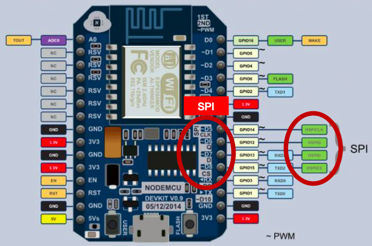
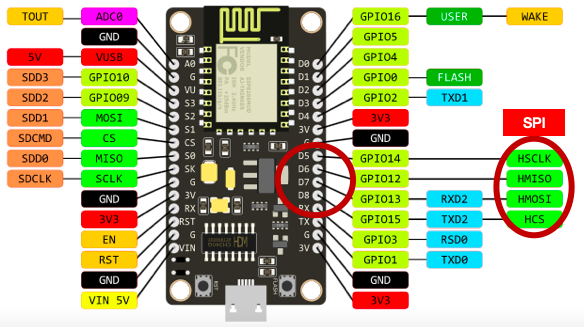
#define TX_PIN D6 // D3 // D5
#define RX_PIN D5 // D4 // D6
#define PWR_PIN D3 // for controlling the power to the Ultrasonic.

SoftwareSerial DYPSensor = SoftwareSerial(RX_PIN, TX_PIN);

#define MAX_TRY_SERIAL 50 // how many cycles of 10ms to wait for before giving up on the sensor (up to 255)
#define MAX_TRY_READING 100 // how many times to try getting a confident reading before giving up and reporting zero (up to 255).

// To collect 30 samples and pick the one with the most votes
#define SAMPLES 30 // Defines how many samples are taken before determining the value that appeared the most and then reporting a reading.
#define MIN_VOTES 20 // How many samples need to be the same to return a good result (suggest 2/3 of SAMPLES)

// define blink error numbers..
const int ERROR_WIFI = 4;
const int ERROR_SENSORS = 5;
const int ERROR_HTTP = 6;

const char* ssid = “YOUR_WIFI_SSID”;
const char* password = “YOUR_WIFI_PASSWORD”;

const char* host = “YOUR_EMONCMS_SERVER”;
const char* apikey = “YOUR_EMONCMS_API_KEY”;
const byte node_id = 35;
const int READING_INTERVAL_SECS = 60; // Default = “60” How long to wait between readings, in seconds.

// Global variables
int SamplesIndex = SAMPLES – 1;
int testValues[SAMPLES];
int testVotes[SAMPLES];
long duration;
int distance = 0;
int last_distance = -1;

void setup() {

#if defined(DEVMODE)
Serial.begin(115200);
#endif

pinMode(LED_BUILTIN, OUTPUT); // Initialize the LED_BUILTIN pin as an output
digitalWrite(PWR_PIN, LOW); // to control power to the sensor

delay(10);

// We start by connecting to a WiFi network
#if defined(DEVMODE)
Serial.println();
Serial.println();
Serial.print(“Connecting to “);
Serial.println(ssid);
#endif

WiFi.begin(ssid, password);

while (WiFi.status() != WL_CONNECTED) {
delay(500);
#if defined(DEVMODE)
Serial.print(“.”);
#endif
}

// TODO: report error if unable to connect to WiFi network
// using blink code.

DYPSensor.begin (9600);

#if defined(DEVMODE)
Serial.println(“”);
Serial.println(“WiFi connected”);
Serial.println(“IP address: “);
Serial.println(WiFi.localIP());
Serial.println(“Finished Setup.”);
#endif

digitalWrite(LED_BUILTIN, HIGH);

} // end of setup

//
// Initialize arrays used to store values and “votes”
//
void InitializeTestValues()
{
// Initialize test values arrays
for (int idx = 0; idx <= SamplesIndex; idx++)
{
testValues[idx] = -1;
testVotes[idx] = 0;
}
}

//
// Reads bytes from RX port and returns a reading in cm
// Returns -1 until a correct value is available
//
int GetDistance() {
byte msb, lsb, checksum, checkcalc, tries = 0;
int distance;

#if defined(DEVMODE)
Serial.print(” Getting reading..”);
#endif

// we want a 255 which is the start of the reading (not msb but saving a byte of storage)..
while (msb != 255) {
// wait for serial..
while ( not DYPSensor.available() && tries < MAX_TRY_SERIAL ) {
delay(10);
tries++;
}
if (tries == MAX_TRY_SERIAL) {
#if defined(DEVMODE)
Serial.println(” TIMED OUT WAITING FOR SERIAL.”);
#endif
return -1;
}
msb = DYPSensor.read();
}

// now we collect MSB, LSB, Checksum..
while ( not DYPSensor.available() ) {
delay(10);
}
msb = DYPSensor.read();

while ( not DYPSensor.available() ) {
delay(10);
}
lsb = DYPSensor.read();

while ( not DYPSensor.available() ) {
delay(10);
}
checksum = DYPSensor.read();

// is the checksum ok?
checkcalc = 255 + msb + lsb;

if (checksum == checkcalc) {
distance = msb * 256 + lsb;
// Round from mm to cm
distance += 5;
distance = distance / 10;

#if defined(DEVMODE)
Serial.print(distance);
Serial.println(“cm “);
#endif

return distance;

} else {

#if defined(DEVMODE)
Serial.println(“bad checksum – ignoring reading.”);
#endif

return -1;
}

} // end of GetDistance()

//
// Adds a sensor value to the testValues array.
// Adds a vote for that reading to the testVotes array.
//
void AddReading(int x)
{
// Either put the value in the first empty cell or add a vote to an existing value.
for (int idx = 0; idx <= SamplesIndex; idx++)
{
// If an empty cell is found, then it is the first time for this value.
// Therefore, put it into this cell and set the vote to 1
if (testValues[idx] == -1)
{
testValues[idx] = x;
testVotes[idx] = 1;
// Exit the For loop
break;
}
// If the cell was not empty, then check to see if the testValue is equal to the new reading
if (testValues[idx] == x)
{
// Add a vote because we got the same reading
testVotes[idx] = testVotes[idx] + 1;
break;
}
};
}

//
// Finds the highest vote and returns the corresponding sensor value
//
int ReturnHighestVote()
{
float valueMax = 0;
int votesMax = 0;
for (int idx = 0; idx <= SamplesIndex; idx++) {
if (testValues [idx] == -1) {
break; // ignore
}
if (testVotes[idx] > votesMax) {
votesMax = testVotes[idx];
valueMax = testValues[idx];
}
}

#if defined(DEVMODE)
Serial.print(“confidence was “);
Serial.println(votesMax);
#endif

if (votesMax >= MIN_VOTES) {
return valueMax;
} else {
// let’s see of the second highest reading is one away from this one..
// first look at valueMax-1..
for (int idx = 0; idx <= SamplesIndex; idx++) {
if (testValues[idx] == valueMax – 1) {
if (testVotes[idx] + votesMax >= MIN_VOTES) {
// we are ok with valueMax..
Serial.print(“One lower voted “);
Serial.println(testVotes[idx]);
return valueMax;
}

}
if (testValues[idx] == valueMax + 1) {
if (testVotes[idx] + votesMax >= MIN_VOTES) {
// we are ok with valueMax..
Serial.print(“One higher voted “);
Serial.println(testVotes[idx]);
return valueMax;
}
}
}
return 0;
}
}

//
// Calls GetDistance repeatedly, adds it to the “test” arrays.
// After SamplesIndex+1 have been read and inserted into the “test” arrays,
// returns the highest voted sensor value.
// Adapted from original voting routines by @JMMS-Karunarathne and @MikeMeinz
// from https://www.codeproject.com/tips/813946/a-method-to-ignore-anomalies-in-an-ultrasonic-dist
//
int GetSensorValue()
{
int current_reading;
InitializeTestValues();
int tries = 0;
// Get the next Maxsample values from the sensor
for (byte idx = 0; idx <= SamplesIndex; idx++)
{
do
{
current_reading = GetDistance();
if (current_reading == -1) tries++;
// or time out after 20 fails…
} while (current_reading == -1.0 && tries < 20);
AddReading(current_reading);
delay(50);
}
return ReturnHighestVote();
}

void loop() {

byte readings;

// power up the ultrasonic sensor..
digitalWrite(PWR_PIN, HIGH);

// get distance from ultrasonic module..
for (readings = 0; readings < MAX_TRY_READING; readings++) {
distance = GetSensorValue(); // Reads MaxSamples values and returns the one that occurred most frequently
if ( distance > 0) break;

#if defined(DEVMODE)
Serial.println(“TRYING AGAIN..”);
#endif

}
// 0 indicates sensor “Out of Range” condition or low confidence

// power down the ultrasonic sensor..
digitalWrite(PWR_PIN, LOW);

#if defined(NO_SEND_SAME)
// now see if the reading was the same as the last one..
if (distance == last_distance) {
// no need to send the result as it is the same as the last one sent..
return;
}
#endif

#if defined(DEVMODE)
Serial.print(“connecting to “);
Serial.println(host);
#endif

// Use WiFiClient class to create TCP connections
WiFiClient client;
const int httpPort = 80;
if (!client.connect(host, httpPort)) {
#if defined(DEVMODE)
Serial.println(“connection failed”);
blink_error(ERROR_HTTP);
#endif
// give up and repeat the whole loop..
return;
}

String url = “/emoncms/input/post.json?apikey=”;
url += apikey;
url += “&node=”;
url += node_id;
url += “&json={“;

if (distance == 0) {
#if defined(DEVMODE)
Serial.println(“BAD READING”);
#endif
url += “read_fail:1}”;
} else {
url += “D:”;
url += distance;
url += “,R:”;
url += readings;
url += “}”;
}


#if defined(DEVMODE)
Serial.println(“Sending: “);
Serial.print(distance);
Serial.println(“cm”);
Serial.print(“Requesting URL: “);
Serial.println(url);
#endif

// This will send the request to the server
client.print(String(“GET “) + url + ” HTTP/1.1\r\n” +
“Host: ” + host + “\r\n” +
“Connection: close\r\n\r\n”);
delay(2000);

#if defined(DEVMODE)
while (client.available()) {
String line = client.readStringUntil(‘\r’);
Serial.print(line);
}
Serial.println();
Serial.println(“closing connection”);
#endif

// now we have sent it, update last_distance..
last_distance = distance;


// quick blink to signify end of cycle..
digitalWrite(LED_BUILTIN, LOW);
delay(100);
digitalWrite(LED_BUILTIN, HIGH);

delay(READING_INTERVAL_SECS * 1000);
}

// report an error by blinking appropriate number (1-255)
void blink_error(uint8_t error_code) {

#if defined(DEVMODE)
Serial.print(“Reporting error: “);
Serial.println(error_code);
#endif

delay(2000);
for (uint8_t i = 0; i < error_code; i++)
{
digitalWrite(LED_BUILTIN, LOW);
delay(400);
digitalWrite(LED_BUILTIN, HIGH);
delay(250);
}

}

DYP-ME007Y TX (Serial output) Ultrasonic Sensor interfacing with Arduino / NodeMCU

There are two main versions of the DYP-ME007Y ultrasonic module (see here to tell the difference) – this article is about interfacing and taking readings from the serial output version.

At the labs, we have been working on interfacing one of these with the NodeMCU – an Arduino-type device with built-in Wifi. This is in order to create a water tank level sensor. The automotive ultrasonic sensor lends itself to this application in that there is no need to add waterproofing – it is already there.

To interface with it we need to convert the 3.3V digital in/outs from the NodeMCU to the 5V required by the DYP-ME007Y. If you were using a 5V Arduino, you wouln’d have to do this. For us, we use a bi-directional logic level converter which is available from eBay. We bought from Electro TV Parts because they stock them in the UK and so shipping is fast.

We are only using two of the four channels on the converter. These are for the two sides of the serial connection between the NodeMCU and the DYP-ME007Y – RX and TX. The converter also needs 5V, 3.3V and GND, which are all available on a pins of the NodeMCU board.

On the NodeMCU, we then need to choose two digital pins for the serial connection, and connect these to the LV (low voltage) side of the converter. The HV side connects to the DYP-ME007Y RX and TX pins. It also needs 5V and GND.

For the serial connection, the pin assigned as TX on the NodeMCU connects (via the converter) to the RX pin on the DYP-ME007Y, and RX on the NodeMCU to TX on the DYP-ME007Y, also via the converter. That’s just how serial works!

Now on to the coding.

We use SoftwareSerial to assign the two digital pins as the TX and RX on the NodeMCU, then we are ready to read the results from the DYP-ME007Y.

#include <SoftwareSerial.h>

// pin assignments. TX on the arduino connects to RX on the sensor, RX to TX.
#define TX_PIN D3
#define RX_PIN D4

SoftwareSerial DYPSensor = SoftwareSerial(RX_PIN, TX_PIN);
const int MAX_TRY_SERIAL = 50; // how many cycles of 10ms to wait for before giving up on the sensor (up to 255)

Here you can see I am using pre-defined constants (D3/D4) for the NodeMCU in the Arduino dev environment. We also define how many times we will try to read the serial before giving up. This allows trapping of the situation were there is nothing coming from the DYP-ME007Y – like if it was not connected.

Now in setup, we start up the serial:

void setup() {

 Serial.begin(19200);
 delay(10);

 DYPSensor.begin(9600);

} // end of setup

We are also starting up the serial connection to the computer it is connected to so we can see debug information.

Our loop looks like this:

void loop() {

 int current_reading;
 current_reading = GetDistance();

 Serial.print(current_reading);
 Serial.println("cm");

 delay(50);
}

..which just calls a subroutine to read the sensor and then prints the result to serial.

GetDistance looks like this:

int GetDistance() {
 byte msb, lsb, checksum, checkcalc, tries = 0;
 int distance;

// we want a 255 which is the start of the reading (not msb but saving a byte of variable storage)..
 while (msb != 255) {
 // wait for serial..
 while ( not DYPSensor.available() && tries < MAX_TRY_SERIAL ) {
 delay(10);
 tries++;
 }
 if (tries == MAX_TRY_SERIAL) {
 Serial.println(" TIMED OUT WAITING FOR SERIAL.");
 return -1;
 }
 msb = DYPSensor.read();
 }

// now we collect MSB, LSB, Checksum..
 while ( not DYPSensor.available() ) {
 delay(10);
 }
 msb = DYPSensor.read();

while ( not DYPSensor.available() ) {
 delay(10);
 }
 lsb = DYPSensor.read();

while ( not DYPSensor.available() ) {
 delay(10);
 }
 checksum = DYPSensor.read();

// is the checksum ok?
 checkcalc = 255 + msb + lsb;

if (checksum == checkcalc) {
 distance = msb * 256 + lsb;
 // Round from mm to cm
 distance += 5;
 distance = distance / 10;

return distance;
 } else {
 Serial.println("bad checksum - ignoring reading.");
 return -1;
 }

} // end of GetDistance()

GetDistance() returns a signed integer of the distance in cm, or -1 if it returned bad data, or the serial read timed out.

It works like this:

  1. Keep reading until we receive a 0xFF which is the start byte.
  2. Now read the most significant byte (msb).
  3. Read the least significant byte (lsb).
  4. Read the checksum.
  5. Calculate the checksum and compare to the one sent from the device.
  6. If checksum matches, it’s a good reading and so return it. If not, return -1.

It makes no attempt to decide whether the sensor has actually sent a meaningful result, just that what we received matched what it sent. More of validating the results in a later article.

Here is the code in full:


/*
 Reads a DYP-ME007Y TX ultrasonic sensor and writes the distance to serial.
 This is the SERIAL VERSION of the sensor
*/

#include <SoftwareSerial.h>

// pin assignments. TX on the Arduino connects to RX on the sensor, RX to TX.
#define TX_PIN D3
#define RX_PIN D4

SoftwareSerial DYPSensor = SoftwareSerial(RX_PIN, TX_PIN);

const int MAX_TRY_SERIAL = 50; // how many cycles of 10ms to wait for before giving up on the sensor (up to 255)

void setup() {

Serial.begin(19200);
 delay(10);

 DYPSensor.begin (9600);

} // end of setup


//
// Reads bytes from RX port and returns a reading in cm

int GetDistance() {
 byte msb, lsb, checksum, checkcalc, tries = 0;
 int distance;

// we want a 255 which is the start of the reading (not msb but saving a byte of variable storage)..
 while (msb != 255) {
 // wait for serial..
 while ( not DYPSensor.available() && tries < MAX_TRY_SERIAL ) {
 delay(10);
 tries++;
 }
 if (tries == MAX_TRY_SERIAL) {
 Serial.println(" TIMED OUT WAITING FOR SERIAL.");
 return -1;
 }
 msb = DYPSensor.read();
 }

// now we collect MSB, LSB, Checksum..
 while ( not DYPSensor.available() ) {
 delay(10);
 }
 msb = DYPSensor.read();

while ( not DYPSensor.available() ) {
 delay(10);
 }
 lsb = DYPSensor.read();

while ( not DYPSensor.available() ) {
 delay(10);
 }
 checksum = DYPSensor.read();

// is the checksum ok?
 checkcalc = 255 + msb + lsb;

if (checksum == checkcalc) {
 distance = msb * 256 + lsb;
 // Round from mm to cm
 distance += 5;
 distance = distance / 10;

return distance;
 } else {
 Serial.println("bad checksum - ignoring reading.");
 return -1;
 }

} // end of GetDistance()


void loop() {

int current_reading;
 current_reading = GetDistance();

Serial.print(current_reading);
 Serial.println("cm");

delay(50);
}


DYP-ME007Y Ultrasonic distance sensor – PWM or Serial?

In order to build a tank level monitoring device, we recently bought a pile of DYP-ME007Y ultrasonic devices. We chose the single sensor version with the automotive sensor used for car parking distance when mounted on the bumper.

Having tried to use both the manual ‘pulse-trigger then measure the response’ and NewPing code, we gave up.

It turns out that there are two (well, actually three) different versions of this module, and it is not that obvious which one is which.

The two versions are Pulse Width Modulation (PWM) and Serial.

The PWM one requires a trigger input to fire it and this flashes the LED once. You then read the pulse from the Echo output.

The Serial version constantly takes readings, and outputs a distance value in mm in serial. The constant readings result in a flashing LED as soon as you apply power.

So – simple test when you apply power only:

No flashes – PWM version

Flashes – Serial version

The PWM version is well-documented, and easy to interface with on Arduino using the NewPing library but the Serial version is not. There is no way of telling from the markings on the board as these show the pin assignments for both versions.

For specification, look for the DYP-ME007TX which shows:

  • Supply voltage 5 v
  • Global Current Consumption 15 mA
  • Ultrasonic Frequency 40k Hz
  • Maximal Range 400 cm
  • Minimal Range 3 cm
  • Resolution 1 cm
  • Baud rate 9600 n,8,1
  • Outline Dimension 43x20x15 mm

However, our testing shows with the automotive sensor the minimum distance is 30cm.

Also useful is the spec of the output which is four 8-bit bytes:

  1. 0xFF: frame start marker byte.
  2. H_DATA: distance data of high eight.
  3. L_DATA: distance data of low 8 bits.
  4. Checksum byte: Value should equal 0xFF + H_DATA + L_DATA  (only lowest 8 bits)

Using emoncms for eco-eye data

emoncms is the data storage, graphing and general visualisations for the OpenEnergyMonitoring project.

For some time here at the Labs we have been using Xively for the data collection and graphing of our energy usage and other sensor stuff. It has really good graphing, plus excellent debug console for checking the incoming data. Beyond this, we have not really been making the best use of it.

We have now switched to emoncms for data collection and graphing. This will give us a better ability to graph multiple feeds together and in any case we will be moving to their sensors at some point in the future.

Their system is open source, so we could choose to host/run our own data collection/storage/graphing but for now an account with them will do. At a later date we can choose to migrate by downloading all our data from them.

After creating an account at emoncms  we set about sending them some data. This is described here and the Perl script we used to connect to Xively has been altered to post to emoncms with JSON type data as described on their API input page. It looks like this:

http://emoncms.org/input/post.json?json={power:200}&apikey=xxxxxxxxxxxxxxxxx

Power is in Watts, but you can pass anything to them in this way, including multiple inputs like {power1:123,power2:456}. For graphing with Xively we separately sent current and (calculated) power, but with emoncms there is no point because any ‘visualisation’ – graph / readout / dial – can be scaled and so if we send power consumption, we can back-calculate to current. This means we are not doubling up the collected data.

Once we started posting data to our account, the feed was listed in the feeds page:

emoncms feeds

..where we could tell it to log the data, and then we could get a graph of the data from the visualisations page:

emoncms graph


Better still, we could make a dashboard:

emoncms dashboard

Dashboards can be made public and so you can publish them if you want (as can individual feeds). Great stuff!

Perl script for eco-eye serial to emoncms is here on Github.


Eco-Eye energy monitor serial data collection

A few years ago my minions installed an Eco-Eye energy monitor in the Labs. We bought it with a serial cable and it has been connected to a Mac Mini to collect data and push it to Cosm (now Xively) via a Perl script. The serial output is 19,200 baud, 8-none-1.Eco-Eye

The supplied serial cable uses a Prolific PL2303 USB to serial chip and so the Mac needs a driver installing which you can get from Prolific here. The current version creates a device named /dev/tty.usbserial (which is much better than the previous cryptic name).

The Eco-Eye data is simple – two bytes which make up the reading are sent every four seconds consisting of msb then lsb representing amps times 100. So, the reading in amps to two decimal places is:

amps = ((byte1 x 256) + byte2) / 100

There is a Perl module to handle posting to Xively called Net::Parchube (because Xively was Cosm was Parchube) which makes that part simple. The hardest part is keeping the bytes in sync – when you start the script you don’t know which one you get first, and sometimes one doesn’t turn up. To handle this, the script has a timeout which makes sure dud readings don’t make it through and corrupt your data. It also averages over seven samples to post a reading about every 30 seconds.

Output will look something like this:

sample: 1, msb: 11, lsb; 18, amps: 28.34
sample: 2, msb: 11, lsb; 36, amps: 28.52
sample: 3, msb: 10, lsb; 244, amps: 28.04
sample: 4, msb: 11, lsb; 24, amps: 28.4
sample: 5, msb: 11, lsb; 28, amps: 28.44
sample: 6, msb: 11, lsb; 8, amps: 28.24
sample: 7, msb: 10, lsb; 240, amps: 28
2014-08-12 10:15:18 avg_amps: 28.28

And on Xively:

xively_data

As you can see, the script also sends a power figure calculated from the amps.

The script runs in the foreground which is not ideal, but it does the job. You can get it from Github here: https://github.com/cllarky/perl-sensor-net/blob/master/eco-eye/serial-cosm.pl

Freedomotic plugin – Resol DL2 reader

The Resol DL2 is a data-logger and web interface for the Resol range of solar controllers, plus some other (similar) stuff they do. The controllers use a proprietary serial bus for communication called VBus, and the DL2 is a way of getting remote access to the information the controller (or group of controllers) connected to it, plus storing this data to an SD card which you can remove or download from.

Resol DL2

There is also an iOS app called VBus Touch which connects to it to give you the current status of the system, plus some short historic data:

Resol VBus Touch screen 1

Resol VBus Touch historic data


This is ok, but there are several things I would like to do:

1. Collect more historic data which can be viewed in graph form real-time.

2. Make decisions based on the water temperature at particular times of the day. For example, turn on the heating to top up the tank with hot water, but only on a cold day when I know there is no sun coming.

I figure that by collecting this data into Freedomotic I can achieve this at some point. But first it has to be collected..

Now, the DL2 has a page which displays real-time data from the controller:

Resol DL2 data

..which is updated from a URL which returns JSON: /dl2/download/download?source=current&output_type=json

As you can see from the image, the version I am running is 2.03. Resol have a later version which connects to their cloud system but I would have to pay for the upgrade. I asked them if the JSON is still there, but they told me I should use the daily data download function (which obviously won’t give me real-time data).

Here is what the output looks like:

{
  "min_time" : 1406906963,
  "max_time" : 1406906963,
  "sieve_interval" : 1,
  "headerset_count" : 1,
  "unique_header_count" : 1,
  "headers" : [
  {
    "id" : "0010_4278_0100",
    "extId" : "00_0010_4278_0100",
    "channel" : 0,
    "destination_address" : 16,
    "source_address" : 17016,
    "protocol_version" : 16,
    "command" : 256,
    "length" : 28,
    "info" : 0,
    "destination_name" : "DFA",
    "source_name" : "DeltaSol BS/DrainBack",
    "fields" : [
    {
      "id" : "000_2_0",
      "name" : "Temperature sensor 1",
      "unit" : " °C"
    },
    {
      "id" : "002_2_0",
      "name" : "Temperature sensor 2",
      "unit" : " °C"
    },
    {
      "id" : "004_2_0",
      "name" : "Temperature sensor 3",
      "unit" : " °C"
    },
    {
      "id" : "006_2_0",
      "name" : "Temperature sensor 4",
      "unit" : " °C"
    },
    {
      "id" : "008_1_0",
      "name" : "Pump speed relay 1",
      "unit" : " %"
    },
    {
      "id" : "009_1_0",
      "name" : "Pump speed relay 2",
      "unit" : " %"
    },
    {
      "id" : "010_1_1",
      "name" : "Sensor 1 defective",
      "unit" : ""
    },
    {
      "id" : "010_1_2",
      "name" : "Sensor 2 defective",
      "unit" : ""
    },
    {
      "id" : "010_1_4",
      "name" : "Sensor 3 defective",
      "unit" : ""
    },
    {
      "id" : "010_1_8",
      "name" : "Sensor 4 defective",
      "unit" : ""
    },
    {
      "id" : "010_1_16",
      "name" : "Emergency store temperature",
      "unit" : ""
    },
    {
      "id" : "010_1_32",
      "name" : "Collector emergency temperature",
      "unit" : ""
    },
    {
      "id" : "011_1_1",
      "name" : "R1 manual operation",
      "unit" : ""
    },
    {
      "id" : "011_1_2",
      "name" : "R2 manual operation",
      "unit" : ""
    },
    {
      "id" : "012_2_0",
      "name" : "Operating hours relay 1",
      "unit" : " h"
    },
    {
      "id" : "014_2_0",
      "name" : "Operating hours relay 2",
      "unit" : " h"
    },
    {
      "id" : "016_2_0",
      "name" : "Heat quantity",
      "unit" : " Wh"
    },
    {
      "id" : "022_1_0",
      "name" : "Status",
      "unit" : ""
    },
    {
      "id" : "023_1_0",
      "name" : "Programme",
      "unit" : ""
    },
    {
      "id" : "024_2_0",
      "name" : "Version",
      "unit" : ""
    }
    ]
  }
  ],
  "headersets" : [
  {
    "timestamp" : 1406906963,
    "packets" : [
    {
      "header_index" : 0,
      "field_values" : [
      {
        "field_index" : 0,
        "raw_value" : 108.100000,
        "value" : "108.1"
      },
      {
        "field_index" : 1,
        "raw_value" : 61.300000,
        "value" : "61.3"
      },
      {
        "field_index" : 2,
        "raw_value" : 65.600000,
        "value" : "65.6"
      },
      {
        "field_index" : 3,
        "raw_value" : 888.800000,
        "value" : "888.8"
      },
      {
        "field_index" : 4,
        "raw_value" : 0,
        "value" : "0"
      },
      {
        "field_index" : 5,
        "raw_value" : 0,
        "value" : "0"
      },
      {
        "field_index" : 6,
        "raw_value" : 0,
        "value" : "0"
      },
      {
        "field_index" : 7,
        "raw_value" : 0,
        "value" : "0"
      },
      {
        "field_index" : 8,
        "raw_value" : 0,
        "value" : "0"
      },
      {
        "field_index" : 9,
        "raw_value" : 0,
        "value" : "0"
      },
      {
        "field_index" : 10,
        "raw_value" : 0,
        "value" : "0"
      },
      {
        "field_index" : 11,
        "raw_value" : 0,
        "value" : "0"
      },
      {
        "field_index" : 12,
        "raw_value" : 0,
        "value" : "0"
      },
      {
        "field_index" : 13,
        "raw_value" : 0,
        "value" : "0"
      },
      {
        "field_index" : 14,
        "raw_value" : 6883.000000,
        "value" : "6883"
      },
      {
        "field_index" : 15,
        "raw_value" : 0,
        "value" : "0"
      },
      {
        "field_index" : 16,
        "raw_value" : 0,
        "value" : "0"
      },
      {
        "field_index" : 17,
        "raw_value" : 1.000000,
        "value" : "1"
      },
      {
        "field_index" : 18,
        "raw_value" : 3.000000,
        "value" : "3"
      },
      {
        "field_index" : 19,
        "raw_value" : 2.030000,
        "value" : "2.03"
      }
      ],
      "data" : [
        57,
        4,
        101,
        2,
        144,
        2,
        184,
        34,
        0,
        0,
        0,
        0,
        227,
        26,
        0,
        0,
        0,
        0,
        0,
        0,
        0,
        0,
        1,
        3,
        203,
        0,
        0,
        0
      ]
    }
    ]
  }
  ]
}

So, I can take this output to collect the info I need into Freedomotic using a custom plugin, and publish it on the event bus to make use of. I decided to make the module flexible enough to collect data from as many devices as there are connected to the DL2, but also so you could specify which info you wanted. You can set this up in the manifest.xml config file.

The module is in Github: https://github.com/cllarky/freedomotic/tree/resol_plugin

resol_data

Next step is to work out how to log and graph the data..


Freedomotic Framework

Freedomotic is described as a ‘Smart Spaces Framework’ and is designed to be the glue to connect together all the elements of your building automation and be the decision engine to control what happens. IFreedomotict is extensible and so any new sensor/actuator/thing you can connect to can be made to work with it. For example it could connect to your Google Calendar to see when you are on holiday, and turn down the heating, or tweet you when the cat comes home.

It is written in Java and can run on Windows, Linux, Mac or anything with a Java environment. Better still, it is open source and has a community of developers supporting and nurturing its growth. Freedomotic is up and running in the Setfire Labs and so we will be hacking about with some plugins and seeing what fun we can have with it.