Following on from the previous post where I was able to read the CAN data, here is a sketch for the NodeMCU and MCP2515_CAN modules to collect the CAN data, interpret it, post it to emoncms, and also replicate it onto additional CAN busses for systems with multiple Sofar Solar ME3000SP inverter/chargers.
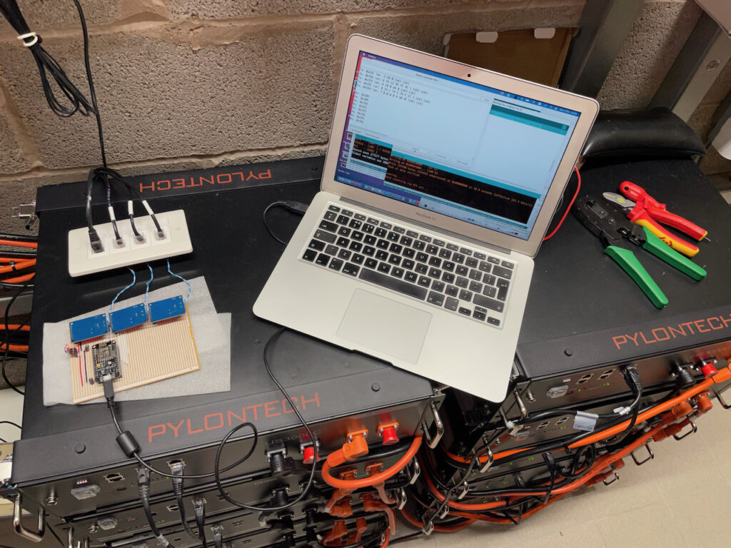
I had planned a simple sketch first, but reliably reading a complete set of CAN data proved less simple than I had imagined.
Catching all the CAN data
The Pylontech battery stack outputs its CAN data once per second. This consists of six CAN packets like this:
CAN ID – followed by 2 to 8 bytes of data:
0x351 – 14 02 74 0E 74 0E CC 01 – Battery voltage + current limits
0x355 – 1A 00 64 00 – State of Health (SOH) / State of Charge (SOC)
0x356 – 4e 13 02 03 04 05 – Voltage / Current / Temp
0x359 – 00 00 00 00 0A 50 4E – Protection & Alarm flags
0x35C – C0 00 – Battery charge request flags
0x35E – 50 59 4C 4F 4E 20 20 20 – Manufacturer name (“PYLON “)
If you are watching the bus, you will also see a 0x305 ID message which is output by the ME3000 once per second. The Pylontech data is sent fairly rapidly, and as was noted in the previous post, and is easy to loose. The MCP2515 has only two receive buffers and so can only hold two messages. If both buffers are full, any additional messages are ignored so the code must clear the buffers quickly during the stream of six messages from the batteries. The messages are always sent in the same order, and it is always the same messages which are lost if the code is too slow in checking. I suspect there are a couple which arrive very soon after the previous message is sent. The priority for the sketch is to collect and buffer the messages, and then process them less frequently.
Here is the first part of loop():
  // If CAN0_INT pin is low, read receive buffer
  if (!digitalRead(CAN0_INT)) {
    while ( CAN0.readMsgBuf(&rxId, &len, rxBuf) != CAN_NOMSG ) {
      store_can();
    }
  }
This is slightly different to the example code for the library (https://github.com/coryjfowler/MCP_CAN_lib/) which does only one check/read per loop() and was found to drop messages – and always the same IDs which the Pylontechs seem to deliver very soon after the previous message. The method above has been very reliable. The routine store_can() puts the CAN message in our own (larger) circular message buffer and does no post-processing – which would make it too slow. Prior to using this polling method in the main loop, I tried an interrupt routine to store to the buffer but this required a different library (which itself needed fixing) and caused new problems with clearing interrupt flags on the MCP2515 – resulting in more lost messages! Polling the interrupt pin on the MCP2515 has been the most reliable method I have found.
Buffering CAN Messages
It is important to buffer the CAN messages so we hold at least one full set of six representing the complete picture of the batteries via CAN. If we have the compete picture, we can pass it to emoncms for reporting. We can also relay it onto additional CAN buses for additional inverter/chargers. The sketch can also print the buffer to the serial port periodically so you can see what is happening (look for the setting INTERVAL_DISPLAY). Each line shows the buffer position, ID, 8 bytes of data, and 2x data length (first for emon post, second for bus replication):
7 35E 00 00 00 00 00 00 00 00 08 08
6 35C 00 00 00 00 00 00 00 00 08 08
5 356 00 00 00 00 0A 50 4E 00 07 07
4 355 14 02 74 0E 74 0E CC 01 08 08
3 351 0E 00 64 00 00 00 00 00 04 04
2 359 02 13 00 00 4A 01 00 00 06 06
1 305 C0 00 00 00 00 00 00 00 02 02
0 305 50 59 4C 4F 4E 20 20 20 08 08
31 35E 00 00 00 00 00 00 00 00 08 08
30 35C 00 00 00 00 00 00 00 00 08 08
29 356 00 00 00 00 0A 50 4E 00 07 00
28 355 14 02 74 0E 74 0E CC 01 08 00
27 351 0E 00 64 00 00 00 00 00 04 00
26 359 02 13 00 00 4A 01 00 00 06 00
25 305 C0 00 00 00 00 00 00 00 02 00
24 305 50 59 4C 4F 4E 20 20 20 08 00
23 35E 00 00 00 00 00 00 00 00 08 08
22 35C 00 00 00 00 00 00 00 00 08 08
21 356 00 00 00 00 0A 50 4E 00 07 07
20 355 14 02 74 0E 74 0E CC 01 08 08
19 351 0E 00 64 00 00 00 00 00 04 04
18 359 02 13 00 00 4A 01 00 00 06 06
17 305 C0 00 00 00 00 00 00 00 02 02
16 305 50 59 4C 4F 4E 20 20 20 08 08
15 35E 00 00 00 00 00 00 00 00 08 08
14 35C 00 00 00 00 00 00 00 00 08 08
13 356 00 00 00 00 0A 50 4E 00 07 07
12 355 14 02 74 0E 74 0E CC 01 08 08
11 351 0E 00 64 00 00 00 00 00 04 04
10 359 02 13 00 00 4A 01 00 00 06 06
9 305 C0 00 00 00 00 00 00 00 02 02
8 305 50 59 4C 4F 4E 20 20 20 08 08
Hardware
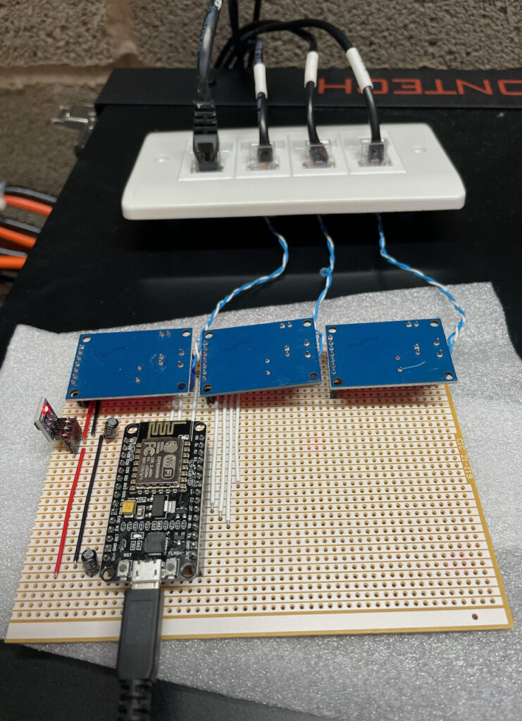
The NodeMCU is connected to the 3x MCP2515_CAN modules in the same way as in the previous post. The only differences here are that the 3.3V supply to them is via a AMS1117-3.3 LDO 5v to 3.3V converter module which is fed from the 5V USB supply. I added 10uF 25V capacitors to the 5V and 3.3V output rails to ensure a stable supply (probably didn’t need these, but I considered it good practice). I am using I/O pins D1, D2, D3, D4 for CAN0 INT, CAN0 CS, CAN1 CS, CAN2 CS. D4 is best as a CS function rather than the INT as it is also used for UART communication during programming. The INT output on the MCP2515_CAN module would be pulled low if there was data on the CAN bus and this would interfere with programming if on an active CAN bus.
Some notes about the system and sketch
Firstly, messing around with your battery system is not a good idea unless you really, really, know what you are doing. You will most likely invalidate any warranties. You also risk:
- destroying your battery system.
- destroying your inverter/chargers.
- burning your house down.
- something worse.
YOU HAVE BEEN WARNED!
The connection to the first CAN bus for reading the data is done using the first CAN interface in listen-only mode and the CAN interface on the Pylontech batteries still connects to the first inverter. The interface also has no bus termination as this is provided at the two ends as usual – the battery, and the inverter. By connecting to the CAN bus this way, we ensure the first inverter is always connected to the batteries. This is important as it ensures the batteries always have a system looking after their interest – like making sure the charge never gets too low (the batteries can force the inverter to charge them from mains if they get too low).
There is one problem inherent in this connection method – the maximum charge and discharge currents are reported to the inverters as-is. This means there is the potential to over charge or over-discharge the batteries. For a small system, this could be a problem and should be considered. For example:
- 2x US2000 batteries = 2x 20A = 40A maximum charge and discharge as reported by the batteries to the inverter.
- if you have 3x inverters, each is sent 40A maximum charge/discharge setting.
- Therefore theoretical maximum charge/discharge current at the batteries is 3x40A = 120A. BAD. You will need to manually reduce your maximum charge and discharge settings on each inverter.
However, if you have a stack of 10x US3000 batteries:
- 10x US3000 batteries = 10x 37A = 370A charge and discharge as reported by the batteries to the inverter.
- if you have 3x ME3000SP inverters, each is capable of 65A max. charge/discharge.
- Total theoretical charge/discharge for the batteries is 3x 65A = 195A which is well within the 370A maximum.
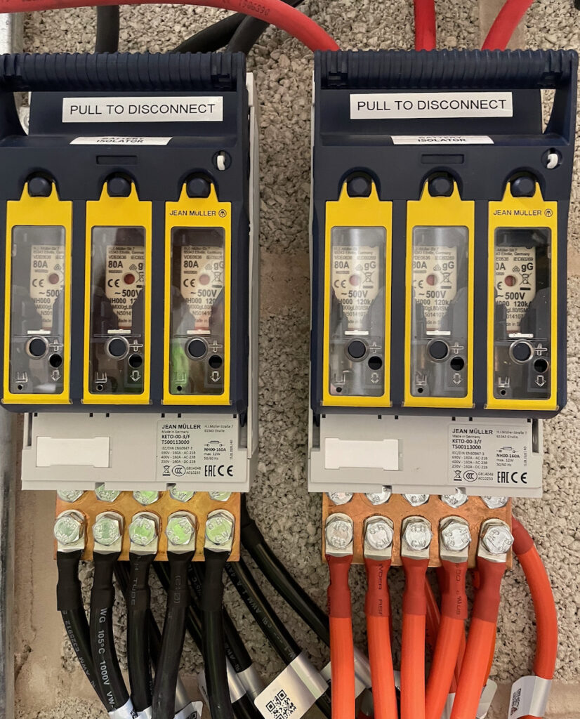
- Of course, your battery cabling needs to be up to the job:
The sketch
The sketch can be found here: https://github.com/setfirelabs/Pylontech_emoncms REMEMBER THE WARNINGS ABOVE BEFORE MESSING WITH YOUR SYSTEM!
The serial output should look something like this:
Ready
IP address: 192.168.1.115
Entering Configuration Mode Successful!
Setting Baudrate Successful!
Entering Configuration Mode Successful!
Setting Baudrate Successful!
Entering Configuration Mode Successful!
Setting Baudrate Successful!
Rx: 0x359
Rx: 0x351
Rx: 0x355
Rx: 0x356
Rx: 0x35C
Rx: 0x35E
Rx: 0x305
Rx: 0x305
Rx: 0x359
Rx: 0x351
Rx: 0x355
Rx: 0x356
Rx: 0x35C
Rx: 0x35E
Rx: 0x305
Rx: 0x305
Rx: 0x359
Rx: 0x351
Rx: 0x355
Rx: 0x356
Rx: 0x35C
Rx: 0x35E
Rx: 0x305

Tx: 0x35E len: 8 50 59 4C 4F 4E 20 20 20 (ok) (ok)
Tx: 0x35C len: 2 C0 0 (ok) (ok)
Tx: 0x356 len: 6 2 13 0 0 4A 1 (ok) (ok)
Tx: 0x355 len: 4 E 0 64 0 (ok) (ok)
Tx: 0x351 len: 8 14 2 74 E 74 E CC 1 (ok) (ok)
Tx: 0x359 len: 7 0 0 0 0 A 50 4E (ok) (ok)
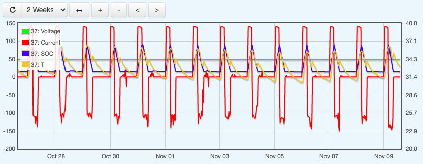
..and have fun graphing!
Before you did this update I came across the same problems as you and ended up using this that made everything so much easier, better and it was fast enough not to loose any messages.
https://www.skpang.co.uk/products/teensy-4-1-triple-can-board-with-240×240-ips-lcd?_pos=24&_sid=65e47e918&_ss=r
Yes, I agree. I have also dropped the NodeMCU / MCP2515_CAN modules in favour of the SKPang board.
I tried using your github code on the NodeMCU and as you’ve mentioned the amount of corrupt packets made it unusable. I’ve also gone and bought the skpang board which looks so much better suited. Before I go and roll my own CAN replication code for it is there already a repo with code for the SKpang board?
Hello, has anyone tried to interface to US5000 Can Bus using this method? Does anyone know if the US5000 uses the same protocol as the US2000 & US3000?
Yes, works in exactly the same way.
Thanks for this very interesting and helpful post.
Somehow using an US3000C connected to a Victron Color Control GX and an Arduino Uno + CanBus shield,
I receive different messages. 0x356 and 0X35C are missing, and I read unknown 0x374 and 0x379 (they are not documented in the Pylontech canbus protocol document).
Here is what I get :
0x351 — 140272017201C201 : 53,2V, 37A, 37A, 45V
0x355 — 32006400 – 50% SoC, 100% SoH
0x359 — 0000000001504E : no alarms ?
0x35E — 50594C4F4E202020 : Manufacturer name (“PYLON “)
0x374 — 3031303100000000 : I have no idea
0x379 — 4A000000 : 74 Ah nominal capacity, I guess
Hello, thanks for taking the time to document your findings. I’m trying to emulate a Pylontech battery pack and I’m comparing between different sources of data dumps to see if there’s aynthing I’ve missed. It looks good, but your dump contains a few unexpected things that I want to make sure aren’t just off-by-one errors in cour code:
– One of your 305 packets contain the string “PYLON “, which according to a datasheet I’ve found belongs in the 35E packet
– The other 305 packet contains the C0 00 word which is probably the state/request flags. Those go in the 35C packet per datasheet
– Your 35C and 35E packets are all 00s which is what I would expect in a 305 packet
– Your buffer contains two data length fields as suffixes to the data. Some 305 packets have a 02 data length and a 00 length. Why would you alter the length field if you’re just relaying messages?
– Your length fields generally seem to belong to different packets than indicated.
Do you have other dumps, where maybe these discrepancies don’t show up? Thanks!
I have ended up discarding the CAN hardware and moving to Teensy and the SKPang triple-can board here: http://skpang.co.uk/catalog/teensy-41-triple-can-board-with-240×240-ips-lcd-p-1592.html
I found with the cheaper hardware that it produced too many errors and could end up in a condition where it just produced rubbish. Here are some recent dumps of V1.2 and V1.3:
Old Pylontechs:
ID: 351 Buffer: 14 2 C0 12 C0 12 C2 1 – Battery voltage + current limits
ID: 355 Buffer: 58 0 5E 0 – State of Health / State of Charge
ID: 356 Buffer: 7A 13 F2 FE 6B 1 – Voltage / Current / Temp
ID: 359 Buffer: 0 0 0 0 6 50 4E – Protection & Alarms
ID: 35C Buffer: C0 0 – Battery charge requests
ID: 35E Buffer: 50 59 4C 4F 4E 20 20 20 – “PYLON ”
New Pylontechs:
ID: 351 Buffer: 10 2 C0 12 C0 12 C2 1 – Battery voltage + current limits
ID: 355 Buffer: 54 0 60 0 0 0 – State of Health / State of Charge
ID: 356 Buffer: 7B 13 E9 FE 6B 1 – Voltage / Current / Temp
ID: 35A Buffer: 0 0 0 0 0 0 0 0 – NEW
ID: 35E Buffer: 50 59 4C 4F 4E 20 20 20 – “PYLON ”
ID: 35F Buffer: 4C 49 1 3 3C 2 AA 0 – NEW
I’ve just started replicating this per the original hardware used and have only now noticed the Skpang board. Are there changes needed to the github code to get it working on the new board?
Yes – it is completely different code.
Thank you! I got it to work in the end and it’s been running for over a year.
> 0x356 – 4e 13 02 03 04 05 – Voltage / Current / Temp
This seems to be incorrect. “04 05” would be a temperature of 128.4 C (263.12 F)
> Tx: 0x356 len: 6 2 13 0 0 4A 1 (ok) (ok)
This one is sane: Temperature is 33.0 C (91.4 F)
Additionally in the buffering sample the message ID doesn’t seem to match the payload:
> 5 356 00 00 00 00 0A 50 4E 00 07 07 4 355 14 02 74 0E 74 0E CC 01 08 08 3 351 0E 00 64 00 00 00 00 00 04 04 <- id says 351, but payload bytes match message 0x355