There are two main versions of the DYP-ME007Y ultrasonic module (see here to tell the difference) – this article is about interfacing and taking readings from the serial output version.
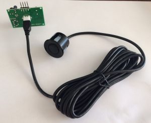 At the labs, we have been working on interfacing one of these with the NodeMCU – an Arduino-type device with built-in Wifi. This is in order to create a water tank level sensor. The automotive ultrasonic sensor lends itself to this application in that there is no need to add waterproofing – it is already there.
To interface with it we need to convert the 3.3V digital in/outs from the NodeMCU to the 5V required by the DYP-ME007Y. If you were using a 5V Arduino, you wouln’d have to do this. For us, we use a bi-directional logic level converter which is available from eBay. We bought from Electro TV Parts because they stock them in the UK and so shipping is fast.
We are only using two of the four channels on the converter. These are for the two sides of the serial connection between the NodeMCU and the DYP-ME007Y – RX and TX. The converter also needs 5V, 3.3V and GND, which are all available on a pins of the NodeMCU board.
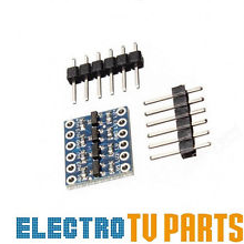
On the NodeMCU, we then need to choose two digital pins for the serial connection, and connect these to the LV (low voltage) side of the converter. The HV side connects to the DYP-ME007Y RX and TX pins. It also needs 5V and GND.
For the serial connection, the pin assigned as TX on the NodeMCU connects (via the converter) to the RX pin on the DYP-ME007Y, and RX on the NodeMCU to TX on the DYP-ME007Y, also via the converter. That’s just how serial works!
Now on to the coding.
We use SoftwareSerial to assign the two digital pins as the TX and RX on the NodeMCU, then we are ready to read the results from the DYP-ME007Y.
#include <SoftwareSerial.h>

// pin assignments. TX on the arduino connects to RX on the sensor, RX to TX.
#define TX_PIN D3
#define RX_PIN D4

SoftwareSerial DYPSensor = SoftwareSerial(RX_PIN, TX_PIN);
const int MAX_TRY_SERIAL = 50; // how many cycles of 10ms to wait for before giving up on the sensor (up to 255)
Here you can see I am using pre-defined constants (D3/D4) for the NodeMCU in the Arduino dev environment. We also define how many times we will try to read the serial before giving up. This allows trapping of the situation were there is nothing coming from the DYP-ME007Y – like if it was not connected.
Now in setup, we start up the serial:
void setup() {

 Serial.begin(19200);
 delay(10);

 DYPSensor.begin(9600);

} // end of setup
We are also starting up the serial connection to the computer it is connected to so we can see debug information.
Our loop looks like this:
void loop() {

 int current_reading;
 current_reading = GetDistance();

 Serial.print(current_reading);
 Serial.println("cm");

 delay(50);
}
..which just calls a subroutine to read the sensor and then prints the result to serial.
GetDistance looks like this:
int GetDistance() {
 byte msb, lsb, checksum, checkcalc, tries = 0;
 int distance;

// we want a 255 which is the start of the reading (not msb but saving a byte of variable storage)..
 while (msb != 255) {
 // wait for serial..
 while ( not DYPSensor.available() && tries < MAX_TRY_SERIAL ) {
 delay(10);
 tries++;
 }
 if (tries == MAX_TRY_SERIAL) {
 Serial.println(" TIMED OUT WAITING FOR SERIAL.");
 return -1;
 }
 msb = DYPSensor.read();
 }

// now we collect MSB, LSB, Checksum..
 while ( not DYPSensor.available() ) {
 delay(10);
 }
 msb = DYPSensor.read();

while ( not DYPSensor.available() ) {
 delay(10);
 }
 lsb = DYPSensor.read();

while ( not DYPSensor.available() ) {
 delay(10);
 }
 checksum = DYPSensor.read();

// is the checksum ok?
 checkcalc = 255 + msb + lsb;

if (checksum == checkcalc) {
 distance = msb * 256 + lsb;
 // Round from mm to cm
 distance += 5;
 distance = distance / 10;

return distance;
 } else {
 Serial.println("bad checksum - ignoring reading.");
 return -1;
 }

} // end of GetDistance()
GetDistance() returns a signed integer of the distance in cm, or -1 if it returned bad data, or the serial read timed out.
It works like this:
- Keep reading until we receive a 0xFF which is the start byte.
- Now read the most significant byte (msb).
- Read the least significant byte (lsb).
- Read the checksum.
- Calculate the checksum and compare to the one sent from the device.
- If checksum matches, it’s a good reading and so return it. If not, return -1.
It makes no attempt to decide whether the sensor has actually sent a meaningful result, just that what we received matched what it sent. More of validating the results in a later article.
Here is the code in full:
/*
 Reads a DYP-ME007Y TX ultrasonic sensor and writes the distance to serial.
 This is the SERIAL VERSION of the sensor
*/

#include <SoftwareSerial.h>

// pin assignments. TX on the Arduino connects to RX on the sensor, RX to TX.
#define TX_PIN D3
#define RX_PIN D4

SoftwareSerial DYPSensor = SoftwareSerial(RX_PIN, TX_PIN);

const int MAX_TRY_SERIAL = 50; // how many cycles of 10ms to wait for before giving up on the sensor (up to 255)

void setup() {

Serial.begin(19200);
 delay(10);

 DYPSensor.begin (9600);

} // end of setup


//
// Reads bytes from RX port and returns a reading in cm

int GetDistance() {
 byte msb, lsb, checksum, checkcalc, tries = 0;
 int distance;

// we want a 255 which is the start of the reading (not msb but saving a byte of variable storage)..
 while (msb != 255) {
 // wait for serial..
 while ( not DYPSensor.available() && tries < MAX_TRY_SERIAL ) {
 delay(10);
 tries++;
 }
 if (tries == MAX_TRY_SERIAL) {
 Serial.println(" TIMED OUT WAITING FOR SERIAL.");
 return -1;
 }
 msb = DYPSensor.read();
 }

// now we collect MSB, LSB, Checksum..
 while ( not DYPSensor.available() ) {
 delay(10);
 }
 msb = DYPSensor.read();

while ( not DYPSensor.available() ) {
 delay(10);
 }
 lsb = DYPSensor.read();

while ( not DYPSensor.available() ) {
 delay(10);
 }
 checksum = DYPSensor.read();

// is the checksum ok?
 checkcalc = 255 + msb + lsb;

if (checksum == checkcalc) {
 distance = msb * 256 + lsb;
 // Round from mm to cm
 distance += 5;
 distance = distance / 10;

return distance;
 } else {
 Serial.println("bad checksum - ignoring reading.");
 return -1;
 }

} // end of GetDistance()


void loop() {

int current_reading;
 current_reading = GetDistance();

Serial.print(current_reading);
 Serial.println("cm");

delay(50);
}
How can I connect the HCSR04 ultrasonic sensor to nodemcu. It has the same issue of 5v. It doesnt have the TX and rx pin on it. Sorry if it’s a noob question. I’m just starting out.
The HCSR04 uses the trig / echo pins, but as you say is a 5v board. As I am doing, use the bi-directional logic level converter on the trig and echo and the standard NewPing library. Good luck!
Hi Jonathan,
trying your sketch but all I get back is bad checksum.
Any idea or hint what I could try else?
Its the right modul, LED kepp flashing when on pwr.
BR Michael
Bad checksum implies you are getting some data. Faulty board?
I faced a problem when Iam interfaced node mcu with ultrasonic sensor to know about water levele for automatic motor on and off Throw IoT, I used pubnub console for demo purpose first I connected the node mcu and relay board, with single power source it was working properl, After I connected two different power supplies in real time operation the data was sended throw pubnub relay data light was blinking but relay was not operated I don’t know what’s the wrong any body have solution ????
Everything is very open with a clear explanation of the issues.
It was truly informative. Your site is extremely helpful.
Thank you for sharing!