Some useful things about this inverter which are not mentioned, or not obvious from the manual. This is based on experience with software version 2.4.
Connecting things up
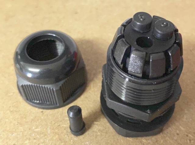
You will need a replacement 20mm cable gland for the mains connection(s) if you are using a 3-core flex as the bung in each cable gland has 3x small holes and so expects 3x single core cables.
The unit comes with 2x M6 cable lugs for 25sqmm DC cables but M8 lugs fit fine (eg. on the end of the Pylontech cables).
Setting up the CTs
The unit comes with 2x CT clamps:
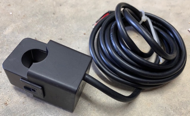
One is for the supply and should be clipped on to your incoming supply live (big fat single-core cable next to your meter). The other is to monitor your generation and so clips to the live wire supply to your PV panels (inside your generation board etc.).
The setup procedure for your inverter includes the steps:
- Make sure all PV is off.
- Turn on battery supply to inverter.
- Turn on mains supply to inverter.
- (now set up time/grid profile/battery)
- Make sure you are consuming at least 200W.
- Turn on the PV and watch it on the display.
What has actually happened here is that the system has worked out which way round the current clamps are (remember you didn’t have to install them a particular way round?)
Now the important part: if you switch off and restart the system, it will go through the same CT configuration again. In fact, there appear to be a number of ‘events’ which cause the CT reconfig:
- Mains off/on
- Battery off/on
- Change work mode
That means that if you cause the CT reconfig when you are exporting power, it will incorrectly read this as an import and then start exporting until it reaches maximum export. Imagine you are currently exporting 2.5kW from your PV – this then ramps up to 2.5kW plus another 3kW from the inverter = 5.5kW export! You do have a G99 relay to stop this don’t you?!?
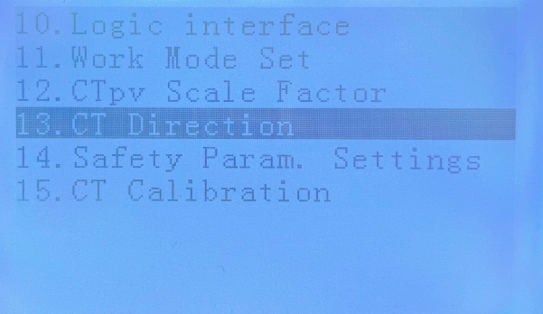
There is a way round this though: FREEZE CT. This is something you should do when you are happy it is configured correctly. Go to Configuration, then down to option 13:
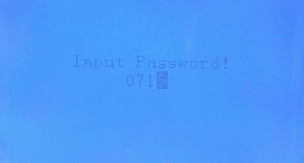
Enter the password:
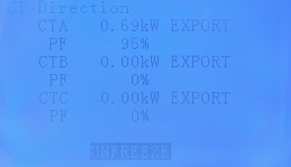
You will see the CTs, and at the bottom ‘UNFREEZE’ (which counter-intuitively means ‘CTs not frozen’:
Press the down button to display ‘FREEZE’:
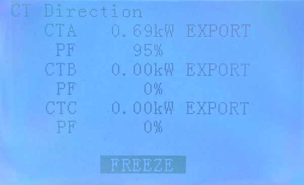
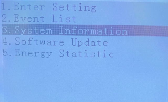
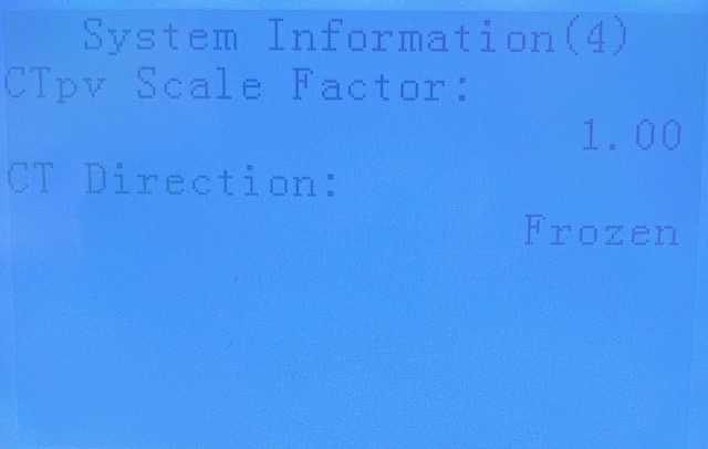
..and then press ‘enter’ to save (then enter again to get off the confirmation screen). You can check the CT direction is frozen from System Information, screen 4:
..which should now show ‘Frozen’:
CTpv isn’t needed
It is possible to use this inverter without the pv sensor. It appears the CTa clamp is the only one used for import/export. This is good news for people who are not able to monitor all (or any) of their generation due to it being connected into different parts of the mains system without a central point for a CT. Obviously you won’t get logged data for the generation and various totals will not be accurate on the system.
Datalogger
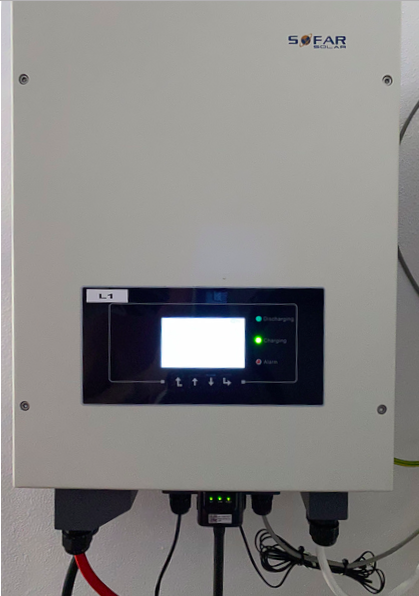
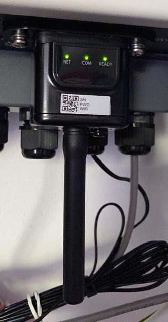
The inverter comes with a datalogger with WiFi. This is something not mentioned in the manual for the inverter. It connects to a DB9 port on the bottom of the unit and once you have it connected to your wifi network, it posts the unit’s data to the Solarman cloud-based system.
Pylontech US3000 and battery capacity
The inverter doesn’t seem to be able to tell the difference between the US2000 and US3000 on the CAN bus at the moment and so incorrectly sets the capacity to 50Ah per battery instead of 75Ah for the larger US3000.
Changing battery settings
Beware: In order to change battery settings, you have to start by selecting the battery type – at this point, the defaults are loaded, overwriting whatever tweaks you previously made. Make sure you go through each parameter again!
Hello! Could you please let me know how I can totally block export to grid from ME3000SP? I do not want any current from my batteries to be exported to grid, no matter how. From the inverter it was easy to accomplish that, by setting reflux to 0kw, but from ME3000SP I have no idea. Thank you!
The default work mode is ‘Auto’ which will stop any export to the grid. Of course, if you are generating more power than your inverter can send to the batteries, it will export what it can’t use.
Thanks for the tip about freezing the CT settings, very helpful.
I’ve found that there is always a small export to the grid when in auto mode, around 40 to 50 watts. Not enough to worry about normally, but it is enough to cause our PV immersion heater diverter to sense an export and then use battery power, rather than solar power, to heat our hot water. It senses import/export using a CT on the tails, adjacent to the one for the ME3000SP.
I’ve been looking through the settings to see if there’s any way to block this small export, but haven’t yet seen an obvious way to do it. Ideally I’d prefer it if there was just a tiny import when it’s running in auto mode, just so the PV hot water diverter can do its thing properly. The work around at the moment is to physically turn off the PV diverter and just use off peak for heating the hot water, but come next spring, when we get more PV generation, it would be good to have this work automatically.
Any tips or ideas anyone has would be welcome, as would links to any sites where people have had a similar issue.
Often there is export as the inverter ramps up it’s charging. This happens particularly on a sunny day when clouds pass, or the switching of a load such as a pump motor which, for example, goes from 1kW to zero in a fraction of a second. Getting your diverter set up correctly is important here.
I have MyEnergi Eddis on each phase which have Advanced >> Supply Grid settings as Export margin = 250W, Export Threshold = 50W and Response Delay = 3s. This seems to avoid the hot water tank drawing power from the batteries. Perhaps your system has similar settings?
Thanks, in case it helps anyone else, I’ve found a fix for this. The problem seems to be caused by the way the ME3000SP reads the CT. There is a setting (menu option 16 in the firmware in my unit) that is labelled “CT Calibration”. This is really a misnomer, as this function adjusts the CT offset around zero watts measured (really amps, in terms of the measured value).
It’s possible to enter the password (the low level user password 0001 is fine) and then adjust the zero offset up and down in increments of 1 watt. I adjusted mine up so that the actual power measured at the incoming supply was close to zero, with the ME3000SP running in auto mode.
This has completely cured the problem, as the ME3000SP is now correctly seeing imports and exports. Before the small offset internally was causing it to incorrectly sense the zero power point.
As a tip for anyone doing this, it does seem to be a bit of an iterative process, and you may need to do as I did and log power for a time, make and adjustment to the CT offset, log for a bit longer, make another adjustment, until you get it spot on. Part of the reason for having to adjust it like this is because every adjustment changes the input/output of the inverter/charger slightly.
Hope this helps.
Hi
I’ve a 6 year old me 3000sp. When it’s fully charged the battery it goes into standby and then fault, red light, and eventually switches off. I’m having to reset it at least twice a day. Also it stays in standby a lot rather than drawing from the battery
Can you recommend someone who could come and resolve this.
Have struggled to get a response from others ive tried. Thank you
Hmm.. No idea who to recommend. You should look at the fault messages on the inverter. Possibly you are ovdercharging?
Hi, can you extend the wire to the current clamps? Regards Mark
Hi Mark,
Yes – the wire can be extended. The manual specifies a particular size of cable, but this is rubbish really since the device is reporting current – any losses from a thin cable are not important since the current is the same. I have successfully extended with 50+ metres of cat6 cable, using a single twisted pair for each clamp.
The ME3000 IS reporting curernt but the CT clamp is generating an AC ‘voltage’ as a proportion of the ‘current’ in the wire it is clamped around. It is therefore very much sensitive to voltage drop and leakage in the cable. Fortunately, the impedance in the cable is usually very low compared to the sense circuit in the ME3000 so it’s effects are minimal. I would not say that the cable requirements are ‘rubbish’ but it does appear in practice to be more tollerent than the manual indicates.
That would depend on whether there is a burden resistor built in to the CT. Is there? There are two types of CT.
Without a burden resistor in the CT, an induced current on the input side of the transformer will produce a current on the output side with a voltage proportional to the (infinite) resistance, limited only by the TVS which is built in to keep things safe.
If the burden resistor is in the ME3000SP, then we are dealing with a current loop and so cable resistance/impedance is less of a problem. That would also allow you to series multiple ME3000SPs on the same CT.
Hi Jonathan,
thanks for sharing your experiences. I am still unsure if I will use the CT approach or passive mode. I already have the consumption and pv productions values available. I own a three phase system, so I would need 3 consumption and 1 production CT. So 4×2 cables in total to extend. Did you really just use one twisted pair per CT, then I could even get away with just one RJ45 Cable. or did you use a twisted for each red & black wire of the CT? Merci fab
I have used CAT6 on some and telephone cable on others. All work. I had some telephone cable which was 6 pair and used a single twisted pair for each CT over 30m. This was a very efficient cabling method!
Hi, Can you change the channels that the Sofar Wifi Works on? I cant find anything specific in the set up and It is sitting on Channel 1 and trying to act as an access point/relay for everything in the house. Its a big house with three other WIFI transmitters wired to the router to get the coverage. It seams to be causing all sorts of contention issues that go away if the Sofar is turned off.
It’s a while since I set them up, but it should only be acting as an access point until the setup is complete. If you are not using Solarman for reporting, you can safely unplug the Wifi dongle from the serial port (and refit the cover plate).
I just checked mine and none is acting as an access point.
I am looking at installing Pylontech US3000C batteries starting with one unit but the Dip switch setting seems a bit confusing some saying its the opposite way round to the manual.
Have you got a pic of what it should be for 1 battery (it obviously will be master) ??
Currently I have a ME3000SP working with 2 Amass GTX2000 but one battery developed a fault so thought I would move on to Pylontech, will the Can bus cable supplied with the ME3000SP still work with the Pylontech batteries or is the Pylontech wired differently??
Many thanks
The supplied cable (RJ11 marked INVERTER to RJ45 marked BAT) will connect fine to the ME3000SP. The battery type should then be set to PYLON, and then check/adjust the battery capacity which I think will be incorrect.
DIP switches are for RS485 baud rate (which you are not using with ME3000SP) and CAN termination which should be left as terminated. All my US3000 and US3000Cs came with DIP switches all set to OFF. However, on the 3000C the DIP switch block has been mounted upside-down which might explain the confusion.
Yes the RJ11 – RJ45 works fine and on the ME3000SP V2.8 firmware the battery option does have Pylon and a US3000 option but no US3000C yet.
The latest version is now V3.0 so maybe that will have the US3000C option in it allowing the deeper DOD of the US3000C as the max in V2.8 is 85%.
Thanks for your info
Interesting. Quite Chinese! I’ve not got my equipment yet so I’m worrying about more mundane stuff: the manual recommends a 100A DC isolator, I assume 2-pole, between battery and inverter – did you bother? Quite an expensive item and not easy to source. Did you put in a 25A AC circuit (mains) as recommended? I would think 16A into consumer unit would be perfectly OK. Maybe 25A is a standard US rating.
I have this fused isolator (and bought from these people who I would recommend): https://www.itstechnologies.shop/collections/pylontech-us2000-us3000-phantom/products/fuse-switch-disconnector-keto-size-00-body-battery-isolator
I found it was worth it because it gives an easy way to turn off the inverter/charger without having to shut down every battery. I am on 16A breakers.
Hi. I have just switched over to Octopus Go so set up my ME3000SP to charge at cheap rate my Pylon batteries (Master 1x US3000c + 2x US2000). I’ve set it up on Time-of-use Mode, a couple of questions that you may be able to help with..
The display requires two dates, start and end, if I set the start date as today what date should I use for the end setting so that the system runs continuously? At the moment I’ve set the end date as one day prior to the start date.
Does the Inverter automatically adjust the time when the clocks change or will I have to update the time myself?
I’ve noticed that having set up the time of use mode when I now check the energy statistics it shows the total load for the day as eg. 3kw but the self use is 0% and the import is 100%.
I’ve emailed Sofar but they haven’t come back with anything yet!
TIA for any help you can offer
Hi Simon,
I think you are correct in with the dates.
I have Time-of-use mode set and I ignored the dates (which have the end date before the start by default). Since we have now passed the clocks change, I can confirm that the time changed automatically – which I expect you also already know!. I think the times are set using the serial dongle.
Can I ask when you used the 3000c as the master, did you continue with the same com cable as you were using with the US2000 battery as a master? I’ve read that using the 3000C with the Sofar ME3000SP you need a differently wired com cable.
I’d appreciate your findings.
Nick
Same cable. There is no difference in the comms.
Sofar Solar inverter showing Alarm. Can you please help in any way.
Hi Simon,
Hope you don’d mind me contacting you?
I have 3X US2000 set up and have just bought a further 3X2000C however they are not playing with each other.
The ME3000SP is running v3.1 but either alone (just 2000C) or as a stack with a ‘C’ battery as master Im still get ID52 errors.
I wonder if you could share an image of your settings or offer some advice?
Thanks in advance!
I am interested in this as I have a setup with a us2000c as a master then 2 X us2000 then 7 X us2000c batteries. Apparently these work as it shows in the manual as long as the us2000 are from bank 2-8 they work together. The question i would like to ask is if you can change the depth of discharge to 95 percent in the inverter will this only apply to the newer type c in the stack.
Any way to buy the right CT clamps? I Need 2 more.
Anybody have the same Problem??
LCD is blinking and don’ t reakting on Buttons.
Half day blinking the other half day working well.
Sorry 4 my realy bad Englisch.
Thx
LCD blinking sounds like a fault. Speak to your supplier. If it is the charge and discharge LEDs then this is ok – it indicates a standby state.
The Current transformers (CT) are I think 1000:1 so 100A becomes a 100mA output. I think this is a standard for this type of thing – Open Energy Monitor, SMA, Sofar Solar all use this standard. It is possible to find them on eBay: Current Transformer
If the CT is for the PV monitoring, it is also possible to calibrate it in the settings.
The CT transformers are actually 3000:1.
Hi, i am having a hyd5000ep with 7.5kwp solar. So far so good, nut since i connected my self made 26s lifepo4 120ah battery i do not see any daily “pie” data values in the solarman app/webportal anymore. Seems an issue with too much losses in power. I guess from battery to house/grid in some way.
Anyone has a solution? Or maybe try the ct calibration? Thanks
Hi
Is it relatively simple to run two me3000sp together, each having six 2.4kw pylontech batteries connected. I find the 3kw max output is causing me to draw from from the grid too often and I reach the end of the day with plenty of battery life left.
Regards
Mick
It is difficult to know what is happening without understanding your setup. In Auto mode, the ME3000SP should continue to discharge until it hits the minimum SOC set for the batteries. It sounds like you have effectively two independent setups, which should play well together without any special setup.
Hello I wonder if you could help, I’m having an issue that has seemed to have developed recently. Around 15;00-1530, regardless of how charged the battery is, the system will start to discharge at full power, the inverter seems to think the demand from the house is 3kw which it isn’t. It has only started to do it over the past week
Or so, I’m not sure what is causing it, tho I think maybe it could be due to my house having 2 separate solar systems ? The battery is connected to one of them on the garage roof, then I have a second system on the main roof, now the garage roof looses the sunshine around 15:00 at this time of year but the system on the main roof is sill in full sunlight, I checked in the loft and it’s still
Generating over 1kw of energy so I am unsure if this is confusing the inverter ? The only way I’ve found to stop it exporting is to switch the system off and then on again and it stops exporting and goes back to normal
Any ideas and help would be greatly appreciated
Have you frozen your CTs? Is your CT in the correct place, measuring the grid current only?
Hi, did you get resolution to this i have the same issue.
SoFar are really bad they do not answer e-mails, when 2022 came my ME3000 has stop charging my battery at night I have tried everything but just can’t get it to work can anyone help Thanks John
Hi
I have just installed an me3000sp (2nd hand on eBay) and it appears to be working but the CTS seem to be reading around 3 times higher than actual. I’m not sure if they are the correct CTS but are marked 100a/100ma. Can these values be adjusted?
Thanks
I have a feeling you should be using 100A/50mV (100A:0.05A) CTs. You can go to Configuration, then down to option 15 – CT Calibration. I am not sure this has the range but is worth a try.
Great post and some really useful tips. I have just installed an ME3000SP and 2x Pylon US3000C. I have upgraded to the latest firmware which is v3.00 There are two things which I’m struggling with.
1) Configuring the ME3000SP to match the US3000C battery’s parameters, specifically the 95% depth-of-discharge (DoD). The only options when adding a Pylon battery are US2000 and US3000 with maximum 80% DoD.
2) Connecting the data logger to the Solarman iPhone app. I have scanned the QR code to add the device to the app, connected my iPhone to the data logger’s access point, started the connection process, but it always fails with an unhelpful error. Has anybody else managed to get this working?
Unfortunately, the ME3000SP will not allow config of 95% DoD.
I have the Solarman working. The process is basically:
1. Connect the data logger, power up the ME3000SP.
2. On your iPhone, go to network settings, find the network it has created and connect to it.
3. Use the web page it displays to select your wifi network and enter the password.
This should allow the data logger to connect to the internet and start posting data. You then to log into Solarman to see your data.
Thanks for your reply, Jonathan. I still can’t get the Solarman data logger working. I can connect to its wireless network fine, but it doesn’t display a webpage into which I can add my main router’s password.
I have also tried opening a browser and going to the IP address of the Solarman data logger (https://10.10.100.152) but just get a “cannot connect to server) error. I also tried turning off “Private Wi-Fi Address” and “Limit IP Address Tracking” in Wireless Settings but still no joy. Any other suggestions?
When the data logger is waiting to be set up, the COM light is solid and the READY is slow flashing.
You join its network with a name like AP_123456.
It asks for a password and you use the one on the label of the logger.
You then must open a web page yourself. Type in the address 10.10.100.254 – this is where you may be going wrong. That is the address of the logger on its network which displays the web portal. The numbers must be exactly the same as I wrote.
Other network settings on my iPhone were the defaults (the access point uses DHCP to give you a network address).
If the lights don’t look as they should, you could perform a factory reset on the logger. To do this, hold the reset button for 10 seconds, let go and watch as the READY light flashes fast. Wait for it to change to COM on, READY flashing slowly then connect.
Thanks – all sorted now. I did figure out that I was using the wrong IP and should be connecting to the router address of 10.10.100.254. But then I didn’t know the username and password to log into the device. Anyway, Google came to the rescue and it’s admin / admin (both now changed…) Thanks for your help!
I managed to configure my ME3000SP for 90% DOD with Pylon batteries (2x US3000C in my case). To do this, I first needed to upgrade to firmware v3.06 which you can download from https://drive.google.com/drive/folders/1-AcNeoWvFcYnqnImUBnOYreo2CHbupfR
NB: This version is a little temperamental, especially when updating from early versions. If you are running pre v3.00 then I would suggest updating to v3.00 first and then v3.06.
I upgraded from v3.00 and it failed at DSP2 the first time, but worked successfully when I ran the upgrade for a second time (which happens for most people apparently). The other difference that I noticed with this version is that there are only .bin files and not the .hex files that you find in other firmware versions. It still seemed to work though.
Thanks Tim – that is very useful.
Hi Tim B,
Can I ask where you are downloading the firmware files from please? I’ve got a HYD3000-ES hybrid inverter with a Pylontech US3000C and trying to resolve the DoD issue, I cannot find any firmware downloads on the Sofar website hoping there may have been an update.
Jonathan,
Great article BTW
Thanks both
Hi Phil K, Sorry for the delay in replying. This Facebook group has lots of really useful information including a repository of firmware versions for various SoFar units. https://www.facebook.com/groups/2477195449252168/
Here’s the post giving the link to the firmware repository for the ME3000SP:
https://www.facebook.com/groups/2477195449252168/permalink/2752924455012598/
and it looks like somebody has posted a Dropbox link for v3.09 (NB: I haven’t tested this one yet, so use at your own risk!)
https://www.dropbox.com/sh/pfmcyj4hays26z5/AACYaYZkXkKvmPQZ1CCXJsG2a?dl=0&fbclid=IwAR2l90Y-cwMwwFNTQBIpHsNYUdLEHJeWMR8LjXgNPQs9DTJWmuiRyMyt1tc
There’s also a very recent post with a link to firmware v3.40 for the HYD-3000-ES
https://www.facebook.com/groups/2477195449252168/permalink/2881275018844207/
Thanks, Tim
Thanks for this Tim.
I am currently running 3.09 on one inverter. This was provided by Sofar as 3.06 seemed to introduce a problem where I experienced ID29 and ID70 Permanent internal faults periodically (unrecoverOCPInstant).
3.09 seems to have fixed this.
Hi
I have an ME3000SP with 16 kWh of storage.
Recently I’ve had power cuts sometimes for a couple of days or more.
Can I connect my PV inverter AC side to an EPS critical loads board?
I’m think that in the event of a power failure and the EPS remaining live the PV inverter will see the power from the EPS output and keep the PV panels operating to supply the house and help preserve the battery.
The contactor would still operate and cut the supply to the grid and isolate the system.
I also have a load dump that I can use to burn of any surplus generation should I be producing more power than I’m using.
Thanks
Interesting thought.
Theoretically it should work but try at your own risk!
The PV inverter will see mains and so should generate power. It would be *really* interesting so see if the ME3000SP would charge the batteries..
Hi Chuck, I would be really interested to hear how this works out for you and particularly whether the ME3000SP ends up charging the batteries when generation exceeds load. I was thinking of doing a very similar setup myself but don’t have a load dump so figured bad things might start happening! What type of load dump do you have?
I have a extra 2000 battery connected to the MS300SP. Each time the inverter runs the battery down, in the evening usually the MS3000 starts AC charging the battery and appers to do this without asking.
Can I stop this feature and just have the battery sit in a depleted state until the solar comes up in the morning?
The battery can call for charge if it is in a very low state of charge.
There is a current draw from the ME3000SP when it is in an idle state – something like 0.5A. With a single US2000, it may be that the ME3000SP is discharging the battery to the point where it is getting so low that it requires charge to protect itself. If that is the case, set your depth of discharge higher on the ME3000SP.
Otherwise, do you have Time of Use mode set to charge to a set level at a particular time of the day?
Hi , I am in the process of setting up a ME3000SP to a Pylontech US3000C battery and am struggling with the connection to the inverter , I have updated the firmware to V2.81 and the battery options does now have the US3000 as an option but whatever I do there is no comms to the inverter (Event ID52 BMS Disconnected)
The Sofar unit I have has the 8 pin CAN connection and the cable I have been given has the following pinout looking from underneath where the exposed copper connectors can be seen
Sofar Side pin 4 – Orange , pin 5 orange / white
Plyontech side pin 7 orange , pin 8 orange / white
I guess they have missed out the gnd but should still get something if the others are correct ,does anyone have the correct pinout for this connection ?
I am using a single US3000C , All dipswitches are off and I am plugging into the A/CAN port on the battery and the CAN port on the Sofar , I have a feeling the cable is incorrect but cant find a pinout anywhere
Any help would be much appreciated
My ME3000SP has an RJ11 (4 pin) for the inverter/charger end, and an RJ45 (8 pin, standard network) for the Pylontechs.
This cable is labelled Inverter at the RJ11 end, and BAT at the RJ45 end. It is a two twisted pair cable and is wired for both RS485 and CAN use.
BAT (RJ45) (As in the US2000 manual)
4 Orange/white CAN-H
5 Orange CAN-L
7 Blue/white 485A
8 Blue 485B
RJ11 (Inverter)
1 Orange/white
2 Orange
3 Blue/white
4 Blue
Bear in mind that the Inverter end will also fit in the RS485 connector which in your case you don’t use!
Hi my 3000sp is set at auto but has stopped charging just have the flashing led’s inverter says all the energy is going to the property. Any ideas? Thanks.
If you are saying the inverter is showing importing when it should show exporting (panels are producing more power than the property needs) then this would indicate a problem with the CT on the property incoming power supply.
Did you freeze it when you set up? If not, a power cycle of the inverter could result in the CT reading in reverse. See the ‘Setting up the CTs’ here: https://www.setfirelabs.com/building-automation/sofar-solar-me3000sp-battery-inverters
Hi, You said that CTpv does not need to be connected. Does mean you can use the ME3000SP without a solar AC inverter? Eg battery storage sytem, where the battery can be charged at night using cheap rate.
If this possible I would need to set the CTPv as Frozen? Before it goes through its setup. My intension is to set up the ME3000SP like this and have a small seperate solar system (DC coupling) to charge the battery.
Down side, it will only power appliances to the maximum output of the ME3000SP and to import power to make up the difference.
Many thanks
Yes, you can do this with Time of Use mode.
The ME3000SP doesn’t really care about what CTpv is doing – this is just for data logging and pretty graphs.
You would think this is the case, but this statement is not true. Have you tried using the ME3000SP in a property that has Solar PV without connecting the PV CT of the ME3000SP, When the ME3000 detects export it starts to charge the batteries, then after a couple of seconds stops charging, waits about 5 seconds then starts charging again…repeat for ever. In this use case it needs to see something on the PV CT else it considers it a minor fault. I don’t know how much the CT PV needs to see, but not all, I have a couple of setups with two solar inverters where one of the solar inverters is in an outbuilding, here I motor just part of the PV generation and the ME3000 is happy to charge with much more than it sees on the CT PV, e.g 1kW on PV CT, charging battery with 2kW (the real amount that would otherwise be exported.
This is all irrelevant if you have no PV and only charge from grid overnight. But once you have an ME3000 you’ll maybe want to try a bit a DIY solar with a few panels and a micro inverter in the garden. It can work if you are aware of this requirement.
A used ME3000 with new Pylontech batteries is such amazing value for money right now. I cannot sing its praises any higher.
Yes- I agree (from experience). The actual charging losses due to this cycle are about 29%.
It seems to follow this pattern:
* Charge 30s (inc. 3s ramp-up)
* Wait 2s
* Standby 6s
* Check charge 2s
* Ramp-up charge 3s..
Taking the ramp up as linear (so equivalent to 1.5s) this gives:
Cycle time: 40s
Charge time: 30-1.5=28.5s
Time efficiency: 71.3%
In Time-of-use mode, overnight charging does not seem to do this. I wrote to Sofar about what looked like a bug. Their response is that this is ‘by design’. Specifically:
‘These model all need to check to make sure that the system is in a safety state,if we don’t eiminate
this check,will affect the system working normally.’
So.. whilst it does do this when there is potential export (eg. PV), it does not when it is just doing an overnight (time-of-use) battery charge. Makes no sense to me..
This is the most usefull posting on this subject I’ve found. I moved up in the world from the Extra 2000 to a US3000c. Great news I thought and connected it. Today it charged really well and is fully charged but does not appear to want to discharge at all. Its sitting in standby, while the house puylls 3kw (cooking dinner) from the grid! I’m going to reset everythig tomorrow and restart the lot from scratch.
Any thoughts on the lack of discharge. it did discharge on the install day but only to 3 of the 6 light on the display.
Sofar are appauling for reply by the stuff the sell is good it appears.
Any thoughts and thanks Jonathan for the very helpfull posting.
mike
If you powered down the ME3000SP then look at the CT settings, make sure they are correct and frozen.
Hi,
Just found this forum and i am wondering if any one has experince with lead acid battery setup.
Set up the ME3000 no problems, but i dont seem to get some of the menu options listed.
Set battery = default
Set capacity in Ah – default is 500 , max 999
set dod to 50% and EPS dod option
I checked the probe was being monitored by disconnecting it and getting battery high temp alarm.
But,
i dont get any of the options listed for max volatges, charging voltages, charging currents etc. all i have for battery setup is above options.
is this right ? the manual does say these parameters should be entered but it does not give me that option for lead acid.
hoping someone has some lead acid battery experience,.
many thanks
john
They are there for a DEFAULT battery setup. The UI is not intuitive though – to set the type, you need to select, then enter, then enter again to get back to the settings. Are you using the back button instead?
hi
It was my mistake. i was so busy worrking out voltages, i didnt realise the two passcodes.i was only using the 0001, whereas i needed to use the 0715 to get to the correct setting menu.
all set up, seems to be doing a good job, currently montoring volatges etc.
only issue i am wondering about is why sometimes the unit only trickle charges the batteries with e.g. 300W whilst 1Kw seems to go back to the grid when the batteries are empty / 50% DOD. i am guessing its some type of battery stress test , but frustrating. other times, it jumps up to 2000W or more charging rate.
many thanks
john
I had same problem, if you enter 0001 as the password you get limited options for batteries, if you enter 0715 as the password, you get the full rage of options.
Hi I’m using my ME3000SP on lead acid batteries there working great only losing up to 4v from my batteries during a full days work but it’s charged again before dark . However is using 2kw at night and it trips between charge and discharge constantly any ideas welcome to stop it charging from the grid.
Hi. Great forum.
I have 6.5KW of Solar and 6 Pylontech batteries (2x US3000C, 4xUS2000). Is there any way to limit the amount of energy exported to the grid from the ME3000SP when the batteries are charged but still allow the system to flex to cover the household energy needs? I need to keep the export below the 3.68KW limit if possible using the battery controller, rather than the two PV system inverters, if possible.
Thanks
If you have already charged your batteries, the options are to export or use a dump load like immersion heaters powered from an Myenergi Eddi. The ME3000SP will not provide export limitation.
Of course, you could always get more battery storage..
Hi Jason
Hi Simon,
Hope you don’d mind me contacting you?
I have 3X US2000 set up and have just bought a further 3X2000C however they are not playing with each other.
The ME3000SP is running v3.1 but either alone (just 2000C) or as a stack with a ‘C’ battery as master Im still get ID52 errors. Moving back to the older batteries works just fine however…
I wonder if you could share an image of your settings or offer some advice so I can replicate it at my end and finally get these blasted things talking!
Thanks in advance!
Hi Geoff,
I too have this very same problem. My ME3000SP has 2 RJ45 connections one for CAN and one for RS485.
The older US2000B works fine on RS485. could not get it to work on CAN at all.
The new US2000C connects for a while on RS485 but then looses comms.
I am at a loose as to whether these newer units are compatable.
Anyone else having problems with the ME3000SP suddenly losing time on the clock? over the past couple of weeks mine has lost between 20 minutes and 40 minutes, usually overnight, at random intervals. It may go for several days showing the right time, then will lose half an hour overnight.
It’s got so bad that I now keep a clock right by the inverter and check the time every morning, resetting it if it’s lost time overnight. I read of others having this problem on Facebook page: https://www.facebook.com/groups/2477195449252168
Someone has suggested that disconnecting the Wifi fixes it, but that then means no access to the Solarman app, so seems a bit extreme. I think the problem may have started around the time the clocks changed, and I did reset the time on the inverter then. The Solarman app is set to the right time zone, but does anyone know if the clock on the ME3000SP syncs to internet time or not?
Losing half an hour or so randomly in the space of a few hours seems as if it might be some sort of glitch, given that the clock keeps good time in between these glitches.
It’s a nuisance, as I first noticed it when the battery wasn’t discharging one morning, after the end of the Economy 7 period, so we were cooking breakfast on peak rate electricity.
From my experience, I think the clocks are set from the dongle. Certainly I have never set mine and they keep good time. I am on a four hour cheap-rate with Octopus Go so would soon know.
In case anyone else is having issues with the clock changing, I have found a fix. I heard mention that if the WiFi dongle was unplugged the problem went away, which I tested and that seems to be correct.
I believe the issue relates to the way that the Sofar servers are trying to reset the time for BST. I don’t change my inverter clock to BST, because our off-peak period is locked to GMT, so if I changed the clock I’d also need to change the Time of Use times.
In case anyone needs a fix for this, then the answer is to leave the clock set to GMT and change the time zone in the Solarman app from the UTCZ Dublin. London etc one, to the one lower down the list that’s just called UTC (no cities after it). This seems to stop the Sofar server from trying to correct what it believes is a clock error.
Since doing this the clock has been keeping good time,, fixed to GMT, with no more sudden changes overnight.
I’ve had problems with my ME3000SP ever since it was installed. It shows incorrect readings almost all of the time. Sometimes the readings simply don’t add up (e.g it will say 500w in from the panels and nothing on the others) or it’s completely nonsensical (e.g it’ll suggest input from the panels at night). Sometimes, the readings do at least add up (i.e they total up to zero correctly), but the numbers seem to be in the wrong place. Occasionally, like now, it’s ‘almost’ correct, e.g it’s saying 170w from the panels (it’s night-time, so that’s wrong), 580w to my usage (that’s about right) and 410w from the grid (which would be right if the panels part were right).
I had the installers replace it with an entirely new unit, but got the exact same response. They now try to ignore me whenever I contact them.
I have 5 x 333 panels (installed previously with just a desktop monitor) and 2 x 2400 batteries (it might be 2 x 1200 = 2400).
I should note that the electricity usage ‘seems’ about right. If I just ignore the ME3000 and focus on the battery lights and meter readings, it seems like I’m at least getting the benefits of my panels. But it’s still very frustrating and leaves me uneasy that the whole thing just isn’t working.
Any thoughts? I’m not an electrician and the original company probably won’t come out to fix it now. I don’t think the software has been updated for years, for example some of the options suggested in other posts don’t even appear on mine (it’s about 3 or 4 years old, and therefore 3 or 4 years out of date).
The CT measuring the generated energy is just there for reporting purposes. I don’t even have mine connected.
The LCD on the front of the ME3000SP works out the numbers based on the things it does know – usually from the CT on the main supply (CTa), the current draw from the batteries, and the the production CT (CTpv).
It seems like you have a problem with your CTpv. This is (as you know) not something affecting your system’s operation, but is causing a reporting/display problem. The problem could be an incorrectly fitted (eg. on wrong cable) CT, or badly extended cable (causing induced readings from other sources) or a faulty CT.
You can check the firmware version from the Information screen – see this page: Sofar Solar ME3000SP Firmware Upgrade Procedure.
Thanks for your reply. I’ll be honest, until I read this page, I thought that the unit was just a faulty run and none of them worked correctly. Reading other replies above, I see that people aren’t having problems, so hopefully this can be fixed.
I don’t have the skill-sets to fix the cables, so I’m trying to contact somebody locally. Sounds like it could be a maintenance job that a skilled technician could fix? I really would like to see the correct figures because I Bitcoin-mine on sunny days. I’d also like to get the figures set up to see if I’m doing things right. Looking at my statistics, I seem to be sending quite a bit back to the grid and I’m not sure if I’m loading correctly at night (I have economy 7 and have it set to fill the batteries during those hours, but it looks like I might not even be using most of it).
It’s good to know that it may just be a display problem. It does seem that way. They fitted a dongle to the unit but I can’t get that working either, because a) I don’t have a modern phone and b) It has no numbers on it, so I don’t know it’s password and c) I can’t detect it from my modem on my PC.
There’s a local company that maintains panels and PV setups. Hopefully they can have a look. I seem to recall the guy fitting it was saying that something wasn’t recording properly, but everything was actually working right. He said my best bet was just to judge from the battery lights and the electricity meter.
Completed installation of a ME3000SP + 280Ah lead-acid battery yesterday and currently in the process of fine tuning. Thank you for the heads-up on fixing the CT direction; essential. For the time being, the maximum charge voltage is set at the recommended Yuasa float voltage of 13.65V per block (54.6V per string) and the fully charged voltage left at the default 52.08V per string. Keen to share the rest of my lead-acid settings and learn from others.
During charging I’m surprised at how often the unit drops into a 2-second standby and ‘Check Charge’ mode before resuming charging .. perhaps every minute or so. Is this normal and can it be adjusted?
I’m finding the 016 UK G98 country setting a little tight for maximum grid voltage when the sun shines hard with occasional nuisance tripping. It’s a familiar problem here with the solar inverter too although the grid is apparently in spec, just. Is there any way to tailor the G98 settings slightly?
Have you thought about converting this board into a groups.io group … could be very useful for the exchange of ideas. Thanks again for the hints and tips. Nigel
A bit late replying to this post, but just in case it helps anyone.
I recently bought a used ME3000SP and while testing it on the bench I also experienced the problem of it going into “check charge” mode at least once per minute.
While I was testing it I did not have a solar PV CT attached since all the advice says the solar PV CT is only used for statistics purposes.
However once the PV CT was connected up the “Check Charge” issue went away.
Hello great forum members,
I have noted that my Inverter Sofar Me3000PS has the voltage reading on its display wrong when high current is flowing.
I have measured the voltage directly on the inverter terminals (not to the battery) by a really good multimeter.
The multimeter reads exactly the same voltage level of the inverter display voltmeter ONLY in case of very few amps are flowing.
But in case of 10A flowing, I read approx 0.5V difference between my multimeter connected across the inverter terminals and inverter display (like 48.38V on inverter terminals and 47.9V on inverter display).
And in case of 20A flowing, I read approx 1V difference between my multimeter connected across the inverter terminals and inverter display (like 48.38V on inverter terminals and 47.4V on inverter display).
And in case of 40A flowing, I read a approx 2V difference between my multimeter connected across the inverter terminals and inverter display (like 48.38V on inverter terminals and 46.4V on inverter display).
My inverter hardware version is V1.0, while the software version is V1.80
Someone has noted the same behaviour on your inverter?
Is there a solution for this problem?
Thanks to all will help me!
Sandro
Hello I forgot to tell you that I am using lead battery with relative battery selection “Default Lead acid”
3.5kw generating from solar
Usage in house 1kw
Going to pylontech battery 0.5kw (1 battery only)
Going to grid 2kw
Could you please let me know why so much excess is going to the grid and only 0.5kw to battery
System is set to auto mode
Many thanks
Assuming US2000 (25A max charge current set by inverter/charger)
25 x 48V = 1200W should be max charge rate.
I am a new to storage systems and after looking at the various options decided to go for the Pylontech solution due mainly to it’s upgradeability. I now have 3x new US3000C batteries and a second-hand Sofar MS3000SP, mainly due to the supply problems sourcing a new one!
I ran through the initial set up on the inverter and ended up with an ID52 comm fault. After a few emails with Sofar china they sent me the V3.0 zip which I successfully uploaded. I went through the same initial setup again using the comm cable (WI0SCAN30RJ1) recommended by Pylontech in their Service support info on communication settings dated 10 Dec 2020, as it seems the US3000C is different to the earlier models with respect to the comms. The same error ID52 showed on start-up.
The latest support email now suggests that as the MS3000SP is quite old, it can only communicate via RS485. They then sent details of the custom cable required to link the ‘old’ inverter to the new US3000C batteries to allow RS485 com. (RJ45 battery pin 7 to Inverter pin 5, battery pin 8 to inverter pin 4).
Custom cable made and checked for continuity etc, still produces ID52 error.
Within the settings on the inverter both ‘Pylon’ and US3000 selected in the sub-menu.
Com settings Inverter:
1 COM ADD 01
2 BAUD RATE 9600
3 DATABITS 8
4 PARITY NONE
5 STOPBITS 1
Dip switches on master US3000C:
1=1 (should give 9600)
2=0
3=0
4=0
I’ve also tried changing the baud rate to 115200 on the inverter along with battery dip 1=0.
Has anyone any thoughts on how to resolve the error?
The US3000C is not old. You should be communicating with the ME3000SP using the CAN interface – connect an RJ45 network cable between the CAN/RS485 port on the ME3000SP to the CAN port on the top battery.
[update] – sorry – been messing with the battery end for too long – it’s about time I wrote a post on the cable since Sofar don’t publish the pinout..
I agree totally with you. The problem is not that the US3000C’s are old it’s the inverter that is the problem according to Sofar. The ME3000SP I am having problems with seems to have a different communications board than that fitted to most of the inverters I’ve seen. It has the data logger/wifi built into the board and not as a separate external plug in logger/wifi module.
The ‘problem’ ME3000SP has a single RJ45 socket for CAN, and then another RJ45 socket for RS485m, both 8P8C.
https://drive.google.com/file/d/1iBQYaaK8OwYsjpbBBvksWZQ59XxiI-0s/view?usp=sharing
The later, more common ME3000SP has a single combined RJ10 (4P4C) socket for CAN/485m.
https://drive.google.com/file/d/1nJhKAGZwqaTG5ixck0wsJOiMg_z_XSAE/view?usp=sharing
The com cable on the newer inverter is RJ45 to RJ10. So the com cable I required to link the ‘old style’ inverter and the master battery will need RJ45 each end.
I hope that is clearer?
Thanks
A customer has a replacement ME300SP AC coupler storage inverter that we have been asked to replace, working with 1 x Pylontech US2000C 48V 2.4kWh lithium storage solar battery. The Pylontech battery has lost all charge due to no activity for a few months through the faulty ME300SP inverter. Is there any trouble shooting information I can be guided by to replace the inverter and re charge the Pylontech battery.
Many thanks
Roger
I am having the exact same problem – My solar ME3000SP is a 2017 model with the RJ45 for both CAN and another for RS485.
My comms cable has just two wires connected to the connectors.
I was communicating perfectly using RS385 to my old pylon tech 2000’s – I now have an additional 3X 2000c and cannot get it to work.
I’ve tried different dip switch combinations, new cables etc etc.
Now going down the firmware route.
If you find a solution, please could you share? likewise ill do the same.
Geoff
I’ve spent so much time on this, I tried both v3.0 and v3.06 firmware with no success at all. Sofar actually recommended v3.0. I went through every option that Sofar support provided via email, even making custom comm cable as per their instructions. Their final answer was that it was just too old to work with the latest “C” model Pylontech product. It seems the whole comm board is different on our old model! I would really like to find a solution as otherwise it looks like I’ll have to find one of the newer models to use the US3000C’s that I’ve bought.
Roger,
Bit of an update.
Managed to update to V2.7 fine – going to 3.06 bricked the inverter (the charge light flashed on boot up and then it remained dead). Had to remove the front cover and remove the comms board and reinstall – this rebooted the inverter and I was able to get back to V2.7. This was on advice of Sofar.
They also confirmed my old inverter would run ‘c’ spec batteries on V2.7.
Full stack of 6 batteries not connect with no ’52 faults’ however they will not discharge or charge and the inverter sits in standby.
The fun continues!!
Geoff.
I found this on another forum:
“Interesting one on my mission to figure out why my US2000C won’t talk to my ME3000SP… Direct from Plyontech.. I can confirm, depending which year model the ME3000SP is, is not compatible with the US-C type batteries. Apparently, the hardware (PCB) in the inverter is incapable of communicating with the hardware in the C type battery, even VIA RS485. So, this is not a faulty battery issue, it is a compatibility issue.”
Also:
” I’m on V3.0 firmware and V1 Hardware, PYLON are trying to get an Serial number range and Hardware Version of devices that won’t work with C series.. till then it’s a bit of a lottery. Some peeps have changed cables and got it working, some have had to get SOFAR to change comms board.”
Hi all,
I am at this stage 6 months on. just purchased a US2000C to go with a US2000B. But the ME3000SP V1 does not want to communicate.
Has anyone got a solution yet?
Hi, I am about to install ME3000SP in 3-phase grid system with 3-phase PV system. I have just 2 CTs in the package, so I need to buy 2 more. Which should I buy, 1:500 or 1:1000 ? Original CTs are STMHALL HY33C1 33E, does it mean that they are 33 ohms? (the CTs that I plan to buy are “rated burden resistance 33 ohms”). Thanks for help.
The ME3000SP is a single phase device – the 2x CTs are 1 for the incoming supply (required to know when there is export which can be used to charge etc.) and 1 for measuring PV generation (used only for reporting and not required).
To properly operate on a 3-phase setup you will need 3x ME3000SP and a method of connecting all 3 to your batteries for monitoring. I think the supplied CTs are 100A:50mA and have no burden resistor. Have a look for SCT-013-000 which has this specification.
I’ve got a couple of Pylontech US2000B batteries alongside my ME3000SP (F/W 2.50). Have noticed that when discharging, the batteries remain equal until about 55-60% and then one of the batteries quickly (c. 5-10 minutes) will discharge to c. 20%. The other one stays at it’s previous charge of c. 60% and has three/four SOC charge lights on. Any ideas appreciated – no idea how long this has been going on for! Thanks.
This doesn’t look good – maybe bad cells. You need the application Batteryview.exe to communicate with the battery to see what’s happening. If under warranty I would go back to your supplier.
Hi Jonathan,
I am having a problem with a set of 4 pylontech US 2000 batteries that are being reported as disconnected from the ME3000SP. The inverter is showing a bit 52 which understand indicate that the BMS is disconnected. We did not have the system installed ourselves as they came with the house. The batteries themselves show no led lights indicating any power present so I assume they somehow have been depleted and won’t charge. Trying to decipher many forums and various PDFs I am guessing this is caused by the Comms issue preventing the inverter from charging them. Any advise of what logical steps to test/determine where the faults can be? There are 4 batteries daisy chained.
Any help is appreciated!
Dear Jonathan,
I have a similar SoFar inverter (HYD 6K-EP), with a back-up battery. During a power cut, the battery will be drained and at the end shut down. Once the power is back, the battery is not restarting.
Is there somewhere an option to auto restart the battery?
regards,
Ruben
What type of battery is it? In the case of the Pylontechs, they will reach a discharge point where they will signal to the inverter that they are not to be discharged (even if the inverter was set to a lower depth of discharge than they would allow).
The BMS in them controls this. They will have the discharge flag set to OFF and the charge flag set to ON. This will mean they automatically start to recharge. If they were left in a discharged state for some time, they would power-off to protect the cells.
Thanks Jonathan for the reply,
I have to check this on the battery, it’s for sure not a Pylontechs. But there is a communication between the battery and inverter and I hope also the discharge flag is part of it.
I find after a firmware a update to stop the control buttons from not operating and the screen from flashing random displays also the back light coming on and off randomly. Now OK.
I find that the battery will charge but won’t give power back when required!!
So keeps charging up. Sometimes rarely it will feed power back but 99% of the time it won’t just drawers from the grid!
It will still feed my iBoost though. Checking settings and I can’t see what may be causing this problem.
Any thoughts would be most appreciated.
Regards
I have now sorted out the not feeding out problem just needed to reset some of the battery settings.
The original problem was the buttons and screen issue. After contacting the supplier of the ME 3000SP I found out it was on the original firmware version 1.00. It has been running for 5 years with no problem till this issue but now updates to version 3.10.
After adding a second battery with the original US2000B plus and now a US2000C. It was then the I had problems with the charging and discharging of both batteries. But now working fine.
My problem now is the original problem of the buttons and screen locking has come back!!
It will work some times so I can only think it’s a hardware problem this too is version V1.00.
Any thoughts on this?
At least I found out from the supplier that it has WIFI capability so can see what’s happening on the Sofar solar app.
Regards.
Ian.
Did you resolve the button and screen locking issue? I’ve got a Me3000sp with a similar problem.
As the buttons are locked I am unable to access the menus to try different firmware. Did Sofar support change the firmware remotely?
Hi – I don’t know if yo might be able to help me
I have an existing set up with a Sofar HYD3600 Inverter with a Pylontech US2000 battery
I now have a new Pylontech US2000C battery to connect to it
I became aware of discussions that I might need a new cable to connect the US2000C to the inverter (it has to be setup as the master battery)
Here is a discussion about it wrt Victron inverters https://community.victronenergy.com/…/can-bus-bms-type…
I have now found some info from Pylontech which suggests that this is also the case for Sofar inverters here:
https://midsummerwholesale.co.uk/…/pylontech-official…
which states “the pin order of GND is changed from Pin2 (US2000/US3000) to 3 / 3 Pin 6(US2000C/US3000C). For direct-pin communication inverter, please make sure the communication cable Pin1/2/3 are NULL. Or alternatively order the correct communication cable (WI0SCAN30RJ1) or external cable kits (BW0US3000BAL0007) from us.”
So it appears I do need a new cable to go from the US2000C to the Inverter – but I am having trouble finding one (it seems to be an RJ45 (Battery) to an RJ10 (Inverter) – does anyone know where to get one from?
Also – I just want reassurancve that I am right (neither Voltacon who sold me the battery or Fresh Eleectrical who set up the original system are being at all helpful – and all the people who sell similar systems seem to be too busy to answer the phone or return my calls and messages)
I made one to the following as per the pin details below and it works with US3000C and ME3000SP.
BAT (RJ45)
4 Orange/white CAN-H
5 Orange CAN-L
7 Blue/white 485A
8 Blue 485B
RJ10 4P4C (Inverter)
1 Orange/white
2 Orange
3 Blue/white
4 Blue
After 3 ,years of pretty trouble free WiFi connection for the Solarman app, I changed my router yesterday and now I cannot reconnect. This sometimes happens after power outages and usually resolves itself eventually. However this cessation has not resolved itself. The router does NOT supply the WiFi signal, this is provided by a mesh set up via BT Whole Home system. I can only assume this issue is to do with the 2.4ghz frequency, but my system allows connection to 2.4 and 5ghz. Any useful suggestions? All other WiFi connections and there are a few, are working just fine.
Hello, my inverter is constantly getting An ID55 and ID77 fault, it happened once before last year but it’s now happening every 2 days, any idea what the issue is ? Kind regards
Thank you for the many useful tips you are providing. I would like to configure my system such that the ME3000SP is able to charge the batteries during off-peak, however, it appears that I cannot simply install a timed change-over relay on the 240v input to the inverter as it doesn’t seem to automatically reset itself after a minor glitch in the mains input, so I have to go through the full manual reset procedure. Is there a work-around for this? Would ‘Freezing’ the CT clamps help?
Thanking you in anticipation of a productive reply.
Timed mode will set a timed charge period and operate in Auto mode the rest of the time.
HELP! I’ve been updating the firmware in my ME3000SP from the original (v1.8) to the latest v3.06. I carried this out in stages first to v2.00, then v2.41, v300, then v3.06. Everything updated perfectly as far as v3.00, but when attempting to update to v3.06 the display went blank part way through the procedure and now the inverter will not boot. The two green LED’s flash followed by nothing.
Any ideas as to how I might be able to resurrect my ME3000SP?
Dear all,
Kindly want to double-check on the me3000sp if it can measure all 3 phases via CTa, CTB and CTc?
Or if alternatively an energy meter could be used instead to tell the me3000sp overall required power??
Many thanks
Hmm. Not sure about that one.
Hi great tips here but I’ve set my me3000sp up and my inverter just constantly says I’m drawing from the grid the more I produce the more it says I’m drawing from the grid! It’s not a ct orientation problem as if I turn the ct around it still read as if I’m drawing from the grid any ideas?
New to this, just installed ME3000sp, all seems well. But possibly one issue. I have 3 rates for electricity from octopus, Cheap rate at night, normal rate during day, and expensive rate early evening.
I have set TOU mode to charge batts during the cheap rate, and if I understand correctly all other times the unit will operate in AUTO mode.
I noticed yesterday my grid consumption was much higher in my expensive evening period than normal ( I have double checked the times in TOU mode ).
In AUTO mode does the ME3000sp ever use grid power to charge the batts or does it ONLY use PV power to charge the batts, Thanks for any advise, regards David
In Auto mode, it should avoid export (charge the batts) and avoid import if there is spare charge in the batteries. The exception to this would be if the batteries are very low and request charge, which could be at any time. Setting an appropriate DOD should avoid this. I work with 12% as a minimum to avoid this.
have a problem with my sofar set up. The isolator switch failed, have replaced it, but now the inverter generation is showing as the same as consumption, even if everything is turned off! Nothing going to grid, batteries charged but seemingly not discharging when needed…..do I need a new inverter, or am I missing something!
Is this website still active?
Once in a while!
Ik had een installatie van een omvormer Sofat ME3000SP met daaraan 3 pylontech US2000 batterijen. Ik heb nu 4 pylontech US2000c batterijen bijgekocht en heb 1 US2000c als master gezet. Nu krijg ik op de omvormer steeds de foutboodschap ID52 BMS disconnected. Hoe kan ik dit verhelpen. Ik heb zowel geprobeerd verbinding te maken via de CAN poort als via de RS/485 poort.
i have ME3000SP but cant access webgui forgot user name and password i setup back 2019 how can i reset user name and password to default and my logger is not usb donglt its fixed to MB. what would default password be for that i can currently login in logger but not the webgui
many thanks
Some very useful info on the ME3000 above! I’ve just connected two of these in parallel so that I get 6kW of power rather than 3kW. Somewhere I’ve read that it’s possible to connect the ‘slave’ inverter to the ‘master’ inverter so that data from both is sent via the wifi loger. I’ve tried to do this by connecting a cable from the 485s connections between the two inverters, but nothing seems to have changed. Any idea how I can achieve this?
I have an ME3000SP inverter which has been running perfectly for the past 6 years with 5 x 2.4KWh Pylontechs and a 6KW panels.
I have recently installed more solar panels on another building complete with inverter. This new system is about 20 meters from Sofar system. Is it possible to connect a third CT via CAT cable to the ME3000SP to monitor the output from the new inverter.
Thanks for any help and advice.
Colin
Hi Jonathan
Fascinating additional info in here, thanks.
I wonder if you mind advising what I am doing wrong – or if the inverter doesn’t support wat I’m trying to do:
I have a relatively normal setup, ME3000SP with x3 Pylontech batteries and PV generation.
I also have an EV charger in the garage which drains the battery when charging as it see this as load on the whole house.
To get around this I got a second CT and arranged as follows:
CTa – main house
CTb – outside circuit excludes PV
I reset the CT sensors as per your description above.
I now get odd results. It appears that:
With PV off, the battery exports, and the display shows the load as “load + battery export”
With PV on at, say 1kW, the display shows load as “load + battery export + PV”…
I also have an “!” next to the CTb reading periodically. It also isn’t reflecting the true load either – 2kW or so shows as 450W.
Can the ME3000SP actually do what I am trying here?
Thanks
Pete
I am not sure CTb can actually be used. Is this documented anywhere?
I think you actually need your additional CT on only the car charger supply and to be in series with CTa to subtract the car charger current.
A ! next to the CT reading I think indicates that the power factor looks wrong – this happens on a correct setup where the current draw is minimal.
Hello all, hello Jonathan, my installation consists of:
– one ME3000SP
– 3.1 kWp of PV on Hoymiles microinverters
– 6 Pylontech US2000C (15 kWh)
My project is to increase my battery capacity using a TezePower pack. I understand that this new pack should not be added in parallel to the existing Pylontech pack.
So I was thinking of paralleling a second ME3000SP for this new battery pack.
Is this concept viable? If so, is it possible to have a diagram? Is there a specific configuration to be made on each of the ME3000SPs?
I sincerely thank you in advance for your advice.
Pascal.