Tag Archives: NodeMCU

Pylontech US2000 / US3000 CAN reading and CAN replication

Following on from the previous post where I was able to read the CAN data, here is a sketch for the NodeMCU and MCP2515_CAN modules to collect the CAN data, interpret it, post it to emoncms, and also replicate it onto additional CAN busses for systems with multiple Sofar Solar ME3000SP inverter/chargers.

Pylontech CAN data reporting and replication

I had planned a simple sketch first, but reliably reading a complete set of CAN data proved less simple than I had imagined.

Catching all the CAN data

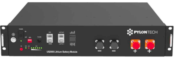
The Pylontech battery stack outputs its CAN data once per second. This consists of six CAN packets like this:

CAN ID – followed by 2 to 8 bytes of data:
0x351 – 14 02 74 0E 74 0E CC 01 – Battery voltage + current limits
0x355 – 1A 00 64 00 – State of Health (SOH) / State of Charge (SOC)
0x356 – 4e 13 02 03 04 05 – Voltage / Current / Temp
0x359 – 00 00 00 00 0A 50 4E – Protection & Alarm flags
0x35C – C0 00 – Battery charge request flags
0x35E – 50 59 4C 4F 4E 20 20 20 – Manufacturer name (“PYLON “)

If you are watching the bus, you will also see a 0x305 ID message which is output by the ME3000 once per second. The Pylontech data is sent fairly rapidly, and as was noted in the previous post, and is easy to loose. The MCP2515 has only two receive buffers and so can only hold two messages. If both buffers are full, any additional messages are ignored so the code must clear the buffers quickly during the stream of six messages from the batteries. The messages are always sent in the same order, and it is always the same messages which are lost if the code is too slow in checking. I suspect there are a couple which arrive very soon after the previous message is sent. The priority for the sketch is to collect and buffer the messages, and then process them less frequently.

Here is the first part of loop():

  // If CAN0_INT pin is low, read receive buffer
  if (!digitalRead(CAN0_INT)) {
    while ( CAN0.readMsgBuf(&rxId, &len, rxBuf) != CAN_NOMSG ) {
      store_can();
    }
  }

This is slightly different to the example code for the library (https://github.com/coryjfowler/MCP_CAN_lib/) which does only one check/read per loop() and was found to drop messages – and always the same IDs which the Pylontechs seem to deliver very soon after the previous message. The method above has been very reliable. The routine store_can() puts the CAN message in our own (larger) circular message buffer and does no post-processing – which would make it too slow. Prior to using this polling method in the main loop, I tried an interrupt routine to store to the buffer but this required a different library (which itself needed fixing) and caused new problems with clearing interrupt flags on the MCP2515 – resulting in more lost messages! Polling the interrupt pin on the MCP2515 has been the most reliable method I have found.

Buffering CAN Messages

It is important to buffer the CAN messages so we hold at least one full set of six representing the complete picture of the batteries via CAN. If we have the compete picture, we can pass it to emoncms for reporting. We can also relay it onto additional CAN buses for additional inverter/chargers. The sketch can also print the buffer to the serial port periodically so you can see what is happening (look for the setting INTERVAL_DISPLAY). Each line shows the buffer position, ID, 8 bytes of data, and 2x data length (first for emon post, second for bus replication):

7 35E 00 00 00 00 00 00 00 00 08 08
6 35C 00 00 00 00 00 00 00 00 08 08
5 356 00 00 00 00 0A 50 4E 00 07 07
4 355 14 02 74 0E 74 0E CC 01 08 08
3 351 0E 00 64 00 00 00 00 00 04 04
2 359 02 13 00 00 4A 01 00 00 06 06
1 305 C0 00 00 00 00 00 00 00 02 02
0 305 50 59 4C 4F 4E 20 20 20 08 08
31 35E 00 00 00 00 00 00 00 00 08 08
30 35C 00 00 00 00 00 00 00 00 08 08
29 356 00 00 00 00 0A 50 4E 00 07 00
28 355 14 02 74 0E 74 0E CC 01 08 00
27 351 0E 00 64 00 00 00 00 00 04 00
26 359 02 13 00 00 4A 01 00 00 06 00
25 305 C0 00 00 00 00 00 00 00 02 00
24 305 50 59 4C 4F 4E 20 20 20 08 00
23 35E 00 00 00 00 00 00 00 00 08 08
22 35C 00 00 00 00 00 00 00 00 08 08
21 356 00 00 00 00 0A 50 4E 00 07 07
20 355 14 02 74 0E 74 0E CC 01 08 08
19 351 0E 00 64 00 00 00 00 00 04 04
18 359 02 13 00 00 4A 01 00 00 06 06
17 305 C0 00 00 00 00 00 00 00 02 02
16 305 50 59 4C 4F 4E 20 20 20 08 08
15 35E 00 00 00 00 00 00 00 00 08 08
14 35C 00 00 00 00 00 00 00 00 08 08
13 356 00 00 00 00 0A 50 4E 00 07 07
12 355 14 02 74 0E 74 0E CC 01 08 08
11 351 0E 00 64 00 00 00 00 00 04 04
10 359 02 13 00 00 4A 01 00 00 06 06
9 305 C0 00 00 00 00 00 00 00 02 02
8 305 50 59 4C 4F 4E 20 20 20 08 08
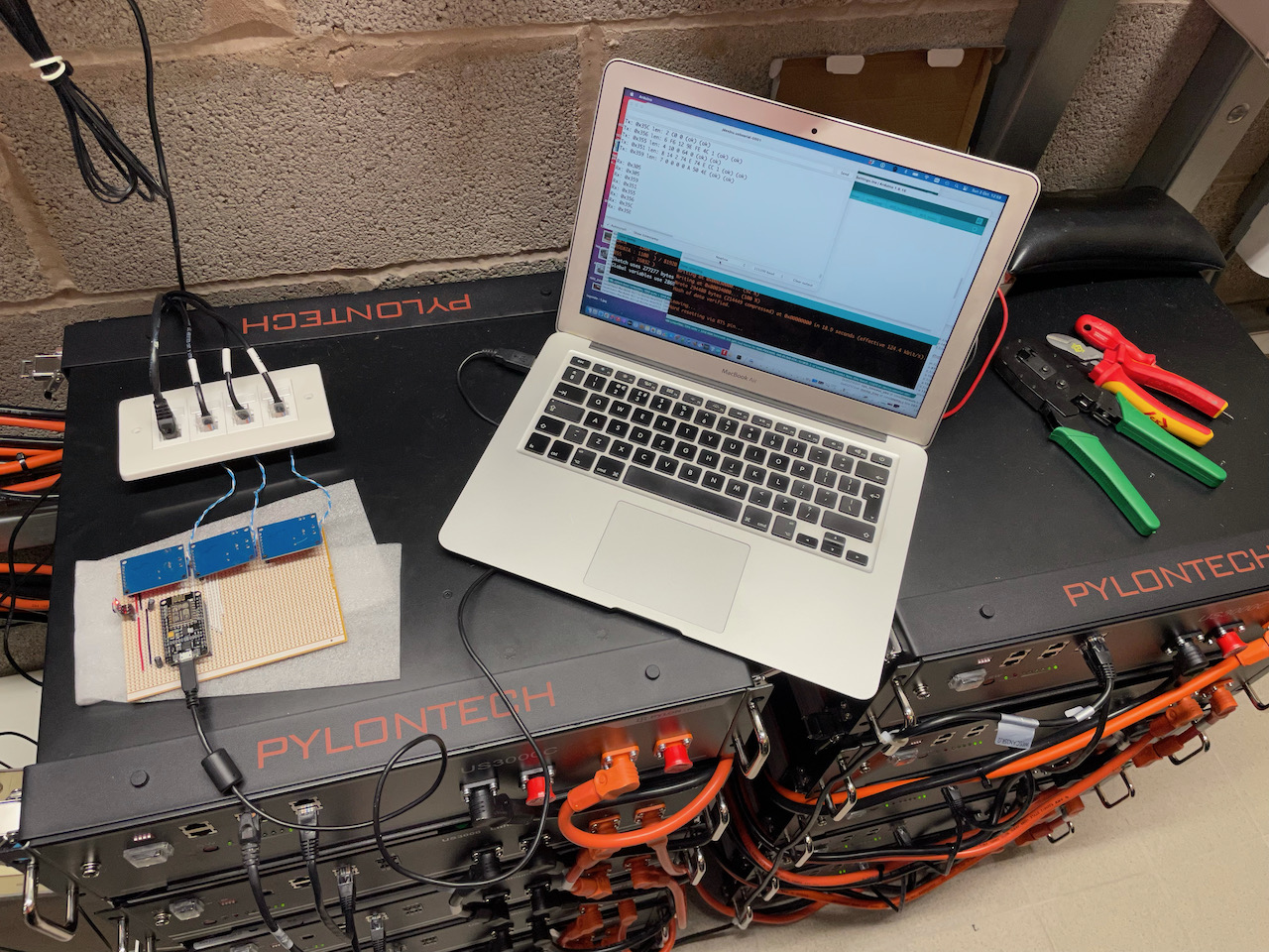
Hardware

NodeMCU and MCP2515 CAN modules

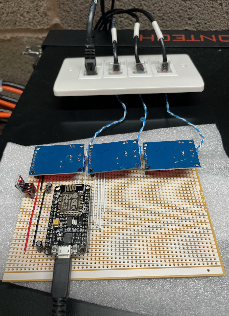
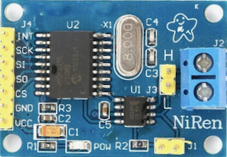
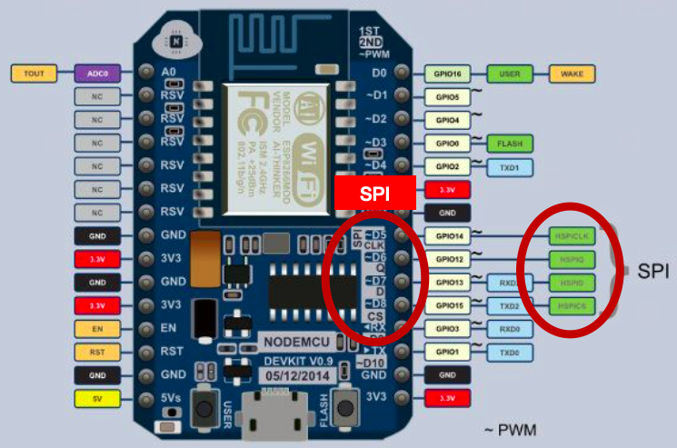
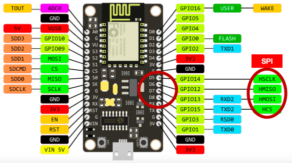
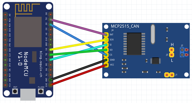
The NodeMCU is connected to the 3x MCP2515_CAN modules in the same way as in the previous post. The only differences here are that the 3.3V supply to them is via a AMS1117-3.3 LDO 5v to 3.3V converter module which is fed from the 5V USB supply. I added 10uF 25V capacitors to the 5V and 3.3V output rails to ensure a stable supply (probably didn’t need these, but I considered it good practice). I am using I/O pins D1, D2, D3, D4 for CAN0 INT, CAN0 CS, CAN1 CS, CAN2 CS. D4 is best as a CS function rather than the INT as it is also used for UART communication during programming. The INT output on the MCP2515_CAN module would be pulled low if there was data on the CAN bus and this would interfere with programming if on an active CAN bus.

Some notes about the system and sketch

Firstly, messing around with your battery system is not a good idea unless you really, really, know what you are doing. You will most likely invalidate any warranties. You also risk:

  • destroying your battery system.
  • destroying your inverter/chargers.
  • burning your house down.
  • something worse.

YOU HAVE BEEN WARNED!

The connection to the first CAN bus for reading the data is done using the first CAN interface in listen-only mode and the CAN interface on the Pylontech batteries still connects to the first inverter. The interface also has no bus termination as this is provided at the two ends as usual – the battery, and the inverter. By connecting to the CAN bus this way, we ensure the first inverter is always connected to the batteries. This is important as it ensures the batteries always have a system looking after their interest – like making sure the charge never gets too low (the batteries can force the inverter to charge them from mains if they get too low).

There is one problem inherent in this connection method – the maximum charge and discharge currents are reported to the inverters as-is. This means there is the potential to over charge or over-discharge the batteries. For a small system, this could be a problem and should be considered. For example:

  • 2x US2000 batteries = 2x 20A = 40A maximum charge and discharge as reported by the batteries to the inverter.
  • if you have 3x inverters, each is sent 40A maximum charge/discharge setting.
  • Therefore theoretical maximum charge/discharge current at the batteries is 3x40A = 120A. BAD. You will need to manually reduce your maximum charge and discharge settings on each inverter.

However, if you have a stack of 10x US3000 batteries:

  • 10x US3000 batteries = 10x 37A = 370A charge and discharge as reported by the batteries to the inverter.
  • if you have 3x ME3000SP inverters, each is capable of 65A max. charge/discharge.
  • Total theoretical charge/discharge for the batteries is 3x 65A = 195A which is well within the 370A maximum.
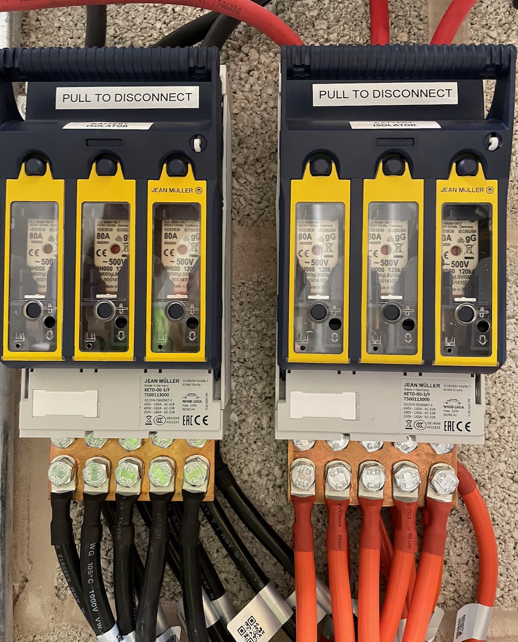
  • Of course, your battery cabling needs to be up to the job:
Battery protection
How to connect 10x Pylontech battery leads to 3x inverters. Terminal covers removed for photo!

The sketch

The sketch can be found here: https://github.com/setfirelabs/Pylontech_emoncms REMEMBER THE WARNINGS ABOVE BEFORE MESSING WITH YOUR SYSTEM!

The serial output should look something like this:

Ready
IP address: 192.168.1.115
Entering Configuration Mode Successful!
Setting Baudrate Successful!
Entering Configuration Mode Successful!
Setting Baudrate Successful!
Entering Configuration Mode Successful!
Setting Baudrate Successful!
Rx: 0x359
Rx: 0x351
Rx: 0x355
Rx: 0x356
Rx: 0x35C
Rx: 0x35E
Rx: 0x305
Rx: 0x305
Rx: 0x359
Rx: 0x351
Rx: 0x355
Rx: 0x356
Rx: 0x35C
Rx: 0x35E
Rx: 0x305
Rx: 0x305
Rx: 0x359
Rx: 0x351
Rx: 0x355
Rx: 0x356
Rx: 0x35C
Rx: 0x35E
Rx: 0x305

Tx: 0x35E len: 8 50 59 4C 4F 4E 20 20 20 (ok) (ok)
Tx: 0x35C len: 2 C0 0 (ok) (ok)
Tx: 0x356 len: 6 2 13 0 0 4A 1 (ok) (ok)
Tx: 0x355 len: 4 E 0 64 0 (ok) (ok)
Tx: 0x351 len: 8 14 2 74 E 74 E CC 1 (ok) (ok)
Tx: 0x359 len: 7 0 0 0 0 A 50 4E (ok) (ok)

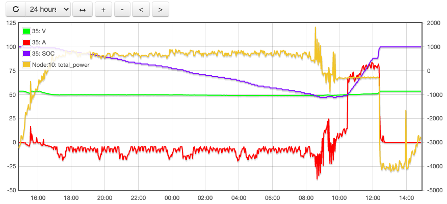
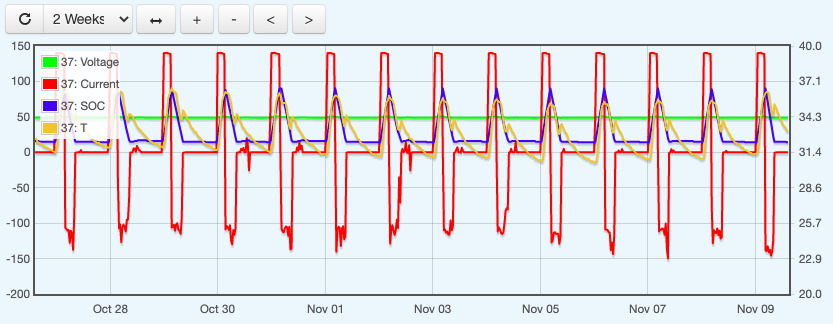
..and have fun graphing!

emoncms pylontech graph

Pylontech US2000/US3000 NodeMCU CAN reader

The Pylontech batteries use either CAN or RS485 to communicate with the inverter. This post is a look at the CAN interface, and how to read that information to allow output to something like emoncms or MQTT.

Pylontech US2000 Battery
Pylontech US2000

Battery communication via the CAN interface is used by the Sofar Solar ME3000 inverter/charger in the setup we have and so the information here is based on this.

There is a Pylontech document specifying the CAN communications around on the internet although it is not that easy to find, and people connected with or in communication with Pylontech seem reluctant to share is, I think because of a NDA. It is, however, out there and if you know what to search for you can find it (ahem, CAN Bus Protocol Pylon low voltage).

The data is output by the battery (or master of a connected battery stack) every 1 second. The data rate is 500kbps and the output information is:

  • Protection Flags (eg. over/under temp)
  • Alarm Flags (eg. over current / voltage, communication fail)
  • Request Flags (eg. force charge)
  • State of Charge and State of Health
  • Voltage, current, Temperature
  • Maximum Voltage, Maximum charge current, Maximum discharge current

The information is for a complete pile (stack of batteries) basis and so there is no information on individual cells, for example.

Reading CAN

Since the CAN bus is a bus (!), multiple communicators can be connected to it. The Pylontech and the ME3000 inverter are the two end-points as they have the resistor terminators. This means another CAN device on the same must be unterminated. (So you can’t for example connect another ME3000 to it and expect it to work.) You can connect into the bus with an unterminated device and read the data without interfering with it. THIS IS GOOD because there is important battery management stuff going on between the inverter/charger and the batteries which you SHOULD NOT MEDDLE WITH. For example, The battery will force a charge from the inverter if it is at a very low state of charge, or if it thinks the state of charge is inaccurate (due to not having reached full charge for a while). Ultimately, you don’t want dead batteries, or a fire on your hands.

MCP2515_CAN Module
MCP2515_CAN Module

The MCP2515_CAN module is a CAN interface which communicates with the NodeMCU via SPI. It can also be powered from 5V or (in our case) 3.3V. J1 is for enabling the terminator resistor so we leave it unconnected. J2 is for the connection to the CAN bus.

SPI (Serial Peripheral Interface) uses four wires for communication. It is a full-duplex, master-slave interface where only one peripheral can communicate with the master at one time. However, multiple peripherals can be connected – and then a fifth wire is used to select which device to talk to – CS or ‘Chip Select’. 

In addition, an interrupt line can be used for the peripheral to signal that there is something to read from it.

The NodeMCU has two SPI interfaces (SPI and HSPI) built-in to the hardware, but one is used internally (SPI – for flash) and so we use the other – HSPI. This is specified here: https://nodemcu.readthedocs.io/en/release/modules/spi/

On the NodeMCU V0.9 board, the useable SPI interface was labelled:

NodeMCU V0.9
NodeMCU V0.9 Pinout

But on the V1.0, only the D lines are labelled:

NodeMCU V1.0 SPI Interface

They are both in the same place though. Here are the assignments:

SignalIO indexESP8266 pin
HSPI CLKD5GPIO14
HSPI /CSD8GPIO15
HSPI MOSID7GPIO13
HSPI MISOD6GPIO12

We are using the NodeMCU as the SPI Master device, so MOSI becomes Master Out and MISO becomes Master In.

MCP2515_CAN J4:

  • INT – interrupt
  • SCK – Serial Clock
  • SI – Slave In
  • SO – Slave Out
  • CS – Chip Select
  • GND – Ground power connection
  • VCC – + Volts connection

We connect the Master Out on the NodeMCU to Slave In and Master In to Slave out:

NodeMCU to MCP2515_CAN module

Powering the interface module

Now, the MCP2515_CAN requires that its power supply matches the voltage of the communicating device. With NodeMCU we are running at 3.3V and so the MCP2515_CAN can also be powered from 3.3V. 

HOWEVER, with the NodeMCU board  powered via the USB connector it is creating its own 3.3V via an on-board regulator from the 5V USB input. This is not sufficient to power the MCP2515_CAN for transmissions on the CAN bus. It is enough for just reading the bus though and so you can see we have powered the board from a 3.3V pin on the NodeMCU. (If you needed more power then a step-down module such as the AMS1117-3.3 LDO module could be connected to the 5V pin to provide the 3.3V for the MCP2515_CAN.

Connecting to the CAN bus

The CAN bus connector on the Pylontech battery is an RJ45 connector – the same as used for networking. CAN uses two wires and these are the blue pair – the centre two pins of the connector. To connect into the bus, we can use a pair of RJ45 sockets connected together with the pair connected to our CAN input:

CAN RJ45 connections

All hardware is now ready! It can be tested using the coryjfowler library https://github.com/coryjfowler/MCP_CAN_lib and the example sketch CAN_receive.ino with the CS and INT data pins set to match ours:

#define CAN0_INT D1
MCP_CAN CAN0(D2);

Now look for the line: if(CAN0.begin(MCP_ANY, CAN_500KBPS, MCP_16MHZ) == CAN_OK) and if you have an 8MHz crystal on your MCP2515_CAN module, change it to:

if(CAN0.begin(MCP_ANY, CAN_500KBPS, MCP_8HZ) == CAN_OK)

Connecting into to the CAN bus with an RJ45 cable from the top battery CAN port to our RJ45 socket, and then connecting the inverter comms cable to the other RJ45 puts us on the CAN bus, and so the sketch can be uploaded and run. If you have been successful, you should get some CAN data in your serial monitor like:

Standard ID: 0x305       DLC: 8  Data: 0x00 0x00 0x00 0x00 0x00 0x00 0x00 0x00
Standard ID: 0x35E       DLC: 8  Data: 0x50 0x59 0x4C 0x4F 0x4E 0x20 0x20 0x20
Standard ID: 0x359       DLC: 7  Data: 0x00 0x00 0x00 0x00 0x04 0x50 0x4E
Standard ID: 0x305       DLC: 8  Data: 0x00 0x00 0x00 0x00 0x00 0x00 0x00 0x00
Standard ID: 0x359       DLC: 7  Data: 0x00 0x00 0x00 0x00 0x04 0x50 0x4E
Standard ID: 0x35E       DLC: 8  Data: 0x50 0x59 0x4C 0x4F 0x4E 0x20 0x20 0x20
Standard ID: 0x351       DLC: 8  Data: 0x14 0x02 0xC8 0x05 0xC8 0x05 0xCC 0x01
Standard ID: 0x305       DLC: 8  Data: 0x00 0x00 0x00 0x00 0x00 0x00 0x00 0x00
Standard ID: 0x35E       DLC: 8  Data: 0x50 0x59 0x4C 0x4F 0x4E 0x20 0x20 0x20
Standard ID: 0x359       DLC: 7  Data: 0x00 0x00 0x00 0x00 0x04 0x50 0x4E
Standard ID: 0x305       DLC: 8  Data: 0x00 0x00 0x00 0x00 0x00 0x00 0x00 0x00
Standard ID: 0x359       DLC: 7  Data: 0x00 0x00 0x00 0x00 0x04 0x50 0x4E
Standard ID: 0x35E       DLC: 8  Data: 0x50 0x59 0x4C 0x4F 0x4E 0x20 0x20 0x20
Standard ID: 0x351       DLC: 8  Data: 0x14 0x02 0xC8 0x05 0xC8 0x05 0xCC 0x01
Standard ID: 0x305       DLC: 8  Data: 0x00 0x00 0x00 0x00 0x00 0x00 0x00 0x00
Standard ID: 0x35E       DLC: 8  Data: 0x50 0x59 0x4C 0x4F 0x4E 0x20 0x20 0x20
Standard ID: 0x359       DLC: 7  Data: 0x00 0x00 0x00 0x00 0x04 0x50 0x4E

A couple of things to point out here: outputting all this junk to the serial port is causing some packets to be missed – the loop is too slow and the CAN buffer is not cleared in time to receive them all (eg. there is no 0x35C ID here) and also the CAN_receive.ino sketch puts our CAN interface into MCP_NORMAL mode – which sends ACKs (we should really be in CAN_LISTEN mode).

Next post – a sketch to decode this data and send it somewhere useful..

Update – post is here: Complete sketch for reading and posting the Pylontech CAN data to emoncms, plus replication to additional CAN busses.