The Pylontech batteries use either CAN or RS485 to communicate with the inverter. This post is a look at the CAN interface, and how to read that information to allow output to something like emoncms or MQTT.
Battery communication via the CAN interface is used by the Sofar Solar ME3000 inverter/charger in the setup we have and so the information here is based on this.
There is a Pylontech document specifying the CAN communications around on the internet although it is not that easy to find, and people connected with or in communication with Pylontech seem reluctant to share is, I think because of a NDA. It is, however, out there and if you know what to search for you can find it (ahem, CAN Bus Protocol Pylon low voltage).
The data is output by the battery (or master of a connected battery stack) every 1 second. The data rate is 500kbps and the output information is:
- Protection Flags (eg. over/under temp)
- Alarm Flags (eg. over current / voltage, communication fail)
- Request Flags (eg. force charge)
- State of Charge and State of Health
- Voltage, current, Temperature
- Maximum Voltage, Maximum charge current, Maximum discharge current
The information is for a complete pile (stack of batteries) basis and so there is no information on individual cells, for example.
Reading CAN
Since the CAN bus is a bus (!), multiple communicators can be connected to it. The Pylontech and the ME3000 inverter are the two end-points as they have the resistor terminators. This means another CAN device on the same must be unterminated. (So you can’t for example connect another ME3000 to it and expect it to work.) You can connect into the bus with an unterminated device and read the data without interfering with it. THIS IS GOOD because there is important battery management stuff going on between the inverter/charger and the batteries which you SHOULD NOT MEDDLE WITH. For example, The battery will force a charge from the inverter if it is at a very low state of charge, or if it thinks the state of charge is inaccurate (due to not having reached full charge for a while). Ultimately, you don’t want dead batteries, or a fire on your hands.
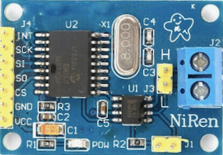
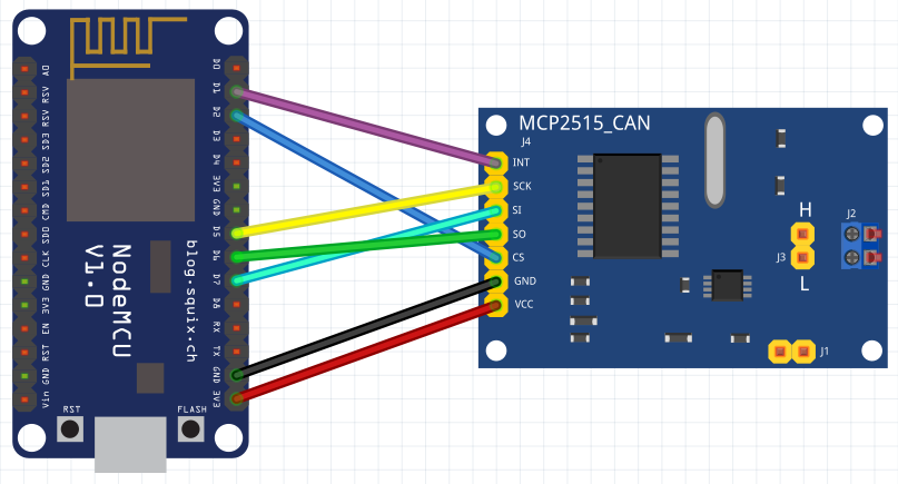
The MCP2515_CAN module is a CAN interface which communicates with the NodeMCU via SPI. It can also be powered from 5V or (in our case) 3.3V. J1 is for enabling the terminator resistor so we leave it unconnected. J2 is for the connection to the CAN bus.
SPI (Serial Peripheral Interface) uses four wires for communication. It is a full-duplex, master-slave interface where only one peripheral can communicate with the master at one time. However, multiple peripherals can be connected – and then a fifth wire is used to select which device to talk to – CS or ‘Chip Select’.
In addition, an interrupt line can be used for the peripheral to signal that there is something to read from it.
The NodeMCU has two SPI interfaces (SPI and HSPI) built-in to the hardware, but one is used internally (SPI – for flash) and so we use the other – HSPI. This is specified here: https://nodemcu.readthedocs.io/en/release/modules/spi/
On the NodeMCU V0.9 board, the useable SPI interface was labelled:
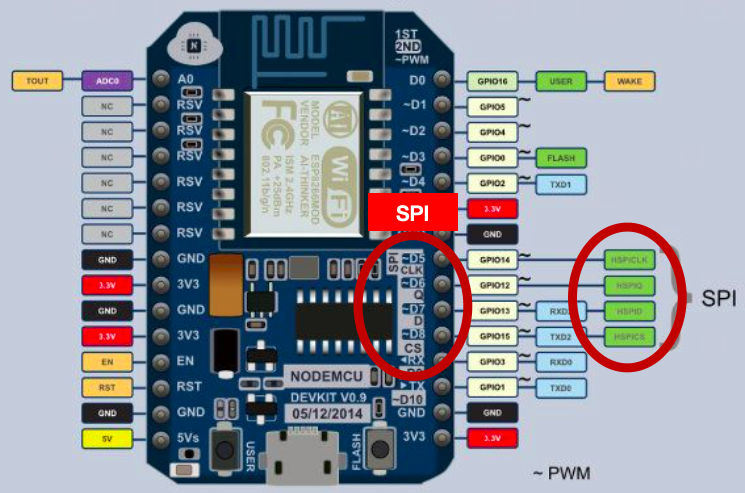
But on the V1.0, only the D lines are labelled:
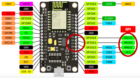
They are both in the same place though. Here are the assignments:
| Signal | IO index | ESP8266 pin |
| HSPI CLK | D5 | GPIO14 |
| HSPI /CS | D8 | GPIO15 |
| HSPI MOSI | D7 | GPIO13 |
| HSPI MISO | D6 | GPIO12 |
We are using the NodeMCU as the SPI Master device, so MOSI becomes Master Out and MISO becomes Master In.
MCP2515_CAN J4:
- INT – interrupt
- SCK – Serial Clock
- SI – Slave In
- SO – Slave Out
- CS – Chip Select
- GND – Ground power connection
- VCC – + Volts connection
We connect the Master Out on the NodeMCU to Slave In and Master In to Slave out:
Powering the interface module
Now, the MCP2515_CAN requires that its power supply matches the voltage of the communicating device. With NodeMCU we are running at 3.3V and so the MCP2515_CAN can also be powered from 3.3V.
HOWEVER, with the NodeMCU board powered via the USB connector it is creating its own 3.3V via an on-board regulator from the 5V USB input. This is not sufficient to power the MCP2515_CAN for transmissions on the CAN bus. It is enough for just reading the bus though and so you can see we have powered the board from a 3.3V pin on the NodeMCU. (If you needed more power then a step-down module such as the AMS1117-3.3 LDO module could be connected to the 5V pin to provide the 3.3V for the MCP2515_CAN.
Connecting to the CAN bus
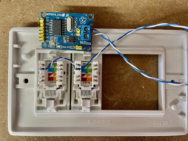
The CAN bus connector on the Pylontech battery is an RJ45 connector – the same as used for networking. CAN uses two wires and these are the blue pair – the centre two pins of the connector. To connect into the bus, we can use a pair of RJ45 sockets connected together with the pair connected to our CAN input:
All hardware is now ready! It can be tested using the coryjfowler library https://github.com/coryjfowler/MCP_CAN_lib and the example sketch CAN_receive.ino with the CS and INT data pins set to match ours:
#define CAN0_INT D1
MCP_CAN CAN0(D2);
Now look for the line: if(CAN0.begin(MCP_ANY, CAN_500KBPS, MCP_16MHZ) == CAN_OK) and if you have an 8MHz crystal on your MCP2515_CAN module, change it to:
if(CAN0.begin(MCP_ANY, CAN_500KBPS, MCP_8HZ) == CAN_OK)Connecting into to the CAN bus with an RJ45 cable from the top battery CAN port to our RJ45 socket, and then connecting the inverter comms cable to the other RJ45 puts us on the CAN bus, and so the sketch can be uploaded and run. If you have been successful, you should get some CAN data in your serial monitor like:
Standard ID: 0x305       DLC: 8  Data: 0x00 0x00 0x00 0x00 0x00 0x00 0x00 0x00
Standard ID: 0x35E       DLC: 8  Data: 0x50 0x59 0x4C 0x4F 0x4E 0x20 0x20 0x20
Standard ID: 0x359       DLC: 7  Data: 0x00 0x00 0x00 0x00 0x04 0x50 0x4E
Standard ID: 0x305       DLC: 8  Data: 0x00 0x00 0x00 0x00 0x00 0x00 0x00 0x00
Standard ID: 0x359       DLC: 7  Data: 0x00 0x00 0x00 0x00 0x04 0x50 0x4E
Standard ID: 0x35E       DLC: 8  Data: 0x50 0x59 0x4C 0x4F 0x4E 0x20 0x20 0x20
Standard ID: 0x351       DLC: 8  Data: 0x14 0x02 0xC8 0x05 0xC8 0x05 0xCC 0x01
Standard ID: 0x305       DLC: 8  Data: 0x00 0x00 0x00 0x00 0x00 0x00 0x00 0x00
Standard ID: 0x35E       DLC: 8  Data: 0x50 0x59 0x4C 0x4F 0x4E 0x20 0x20 0x20
Standard ID: 0x359       DLC: 7  Data: 0x00 0x00 0x00 0x00 0x04 0x50 0x4E
Standard ID: 0x305       DLC: 8  Data: 0x00 0x00 0x00 0x00 0x00 0x00 0x00 0x00
Standard ID: 0x359       DLC: 7  Data: 0x00 0x00 0x00 0x00 0x04 0x50 0x4E
Standard ID: 0x35E       DLC: 8  Data: 0x50 0x59 0x4C 0x4F 0x4E 0x20 0x20 0x20
Standard ID: 0x351       DLC: 8  Data: 0x14 0x02 0xC8 0x05 0xC8 0x05 0xCC 0x01
Standard ID: 0x305       DLC: 8  Data: 0x00 0x00 0x00 0x00 0x00 0x00 0x00 0x00
Standard ID: 0x35E       DLC: 8  Data: 0x50 0x59 0x4C 0x4F 0x4E 0x20 0x20 0x20
Standard ID: 0x359       DLC: 7  Data: 0x00 0x00 0x00 0x00 0x04 0x50 0x4E
A couple of things to point out here: outputting all this junk to the serial port is causing some packets to be missed – the loop is too slow and the CAN buffer is not cleared in time to receive them all (eg. there is no 0x35C ID here) and also the CAN_receive.ino sketch puts our CAN interface into MCP_NORMAL mode – which sends ACKs (we should really be in CAN_LISTEN mode).
Next post – a sketch to decode this data and send it somewhere useful..
Update – post is here: Complete sketch for reading and posting the Pylontech CAN data to emoncms, plus replication to additional CAN busses.
Can’t wait to se the next post. I’m hoping to read the data and then send it on to an Eltek charger which runs on a bus speed of 125KBPS not the 500KBPS of the Pylontech.
Not long now – I have a quick-and-dirty program which interprets and posts to emoncms. Just some final testing..
Any update to this — needed some sample data.
Data considered for below
Standard ID: 0x351 DLC: 8 Data: 0x14 0x02 0xC8 0x05 0xC8 0x05 0xCC 0x01
From one the document had 0x351 as following
CAN ID: 0x351
Data 0 & 1– Battery Charge Voltage (data type : 16bit unsigned int, byte order : little endian, unit : 0.1V)
Data 2&3 — DC Charge Current Limitation (data type : 16bit signed int, 2’s complement, byte order : little endian, scale factor : 0.1A
Data 4 & 5 — DC Discharge Current Limitation (data type : 16bit signed int, 2’s complement, byte order : little endian, scale factor : 0.1A
From the above sample, we do see
Voltage 14 02 ( 0214 Hex) = 532 so it is 53.2v
Current C8 05 (05C8 Hex) = 1480 so it is 148.0 A (not sure whether this is correct)
But we are expected to see Data byte 6 and 7 to be zero but above we have data.
Update is here, including some data: https://www.setfirelabs.com/green-energy/pylontech-can-reading-can-replication
The current of 148.0A is a stack of 4x US3000 – 4x 37A = 148.0A.
It’s also interesting.
In the future, it would be possible to output both from the battery and from the inverter to emoncms or similar.
Inverter outputs using the serial interface which connects to Solarman. You would have to replace this.
Thanks, In the end I used a Teensy that was able to operate fast enough to not loose any data.
I support! I will also look forward to the continuation of the article).
I have a Sofar Solar 15kTL-3PH inverter, it is three phase, but it also works with the Polyntech protocol.
I want to write a converter from a different type of BMS, which does not have the Polyn protocol …
I would like to understand what each byte is responsible for)
And its correspondence to the real value of Voltages, Currents, SOC, SOH, Alarms, etc.
Thanks. New article is here: https://www.setfirelabs.com/green-energy/pylontech-can-reading-can-replication
CAN ID: 0x35C
Is single byte output
bit 7 Battery charge enable
bit 6 Battery discharge enable
bit 5 Battery charge immediately I
bit 4 Battery charge immediately II
rest empty
Data “1” means on, “0” means off. For example (“1”表示使能,“0”表示关闭): If Bit 7 data is “0”, it means the charge current limit should be 0A.
If Bit 6 data is “0”, it means the discharge current limit should be 0A.
If Bit 5 data (level 1 forced charging) function is turned on, the maximum charging current allowed for level 1 force charging needs to be controlled;
The Bit4 (level 2 forced charging) function is turned on, the maximum charging current allowed for level 2 forced charging needs to be controlled.
FYI I saw a you-tube about using Pylontech serial port. https://www.youtube.com/watch?v=7VyQjKU3MsU. He uses Arduino to send and receive serial commands and parse response. He converts to JSON and ultimately MQTT.
His work is at: https://github.com/irekzielinski/Pylontech-Battery-Monitoring
Thanks for pointing this out. I have had a look at it.
I have seen other work on via the console port and this certainly provides a far greater granularity of data which is not available via CAN.
The reason for working with the CAN interface was to collect the data for reporting at the same time as replicating it onto additional CAN busses for multiple inverter/chargers, eg. with a 3-phase setup using one battery pile and 3x ME3000SP.
Do you know if the Pylontech US3000C uses the same communications as sister battery US2000C?
According to Solark, US brand of hybrid inverters, the US3000C is compatible!
They cannot confirm if sister battery US2000C would be compatible with SolArk 12 kW Outdoor version.
Do you or anyone have any clues on this?
I have used US3000, US3000C, US5000 which (from the point of view of a ME3000SP inverter) are all the same, and are treated exactly the same by the inverter as they output the same CAN data.
There is at least one additional parameter output by the US5000 but I have not looked into this yet.